
 | ||
The Sparse Matrix Converter is an AC/AC converter which offers a reduced number of components, a low-complexity modulation scheme, and low realization effort . Invented in 2001 by Prof Johann W. Kolar , sparse matrix converters avoid the multi step commutation procedure of the conventional matrix converter, improving system reliability in industrial operations. Its principal application is in highly compact integrated AC drives.
Contents
Characteristics
Matrix Converter
Matrix converter is a device which converts AC input supply to the required variable AC supply as output without any intermediate conversion process whereas in case of Inverter which converts AC - DC - AC which takes more extra components as diode rectifiers, filters, charge-up circuit but not needed those in case of matrix converters
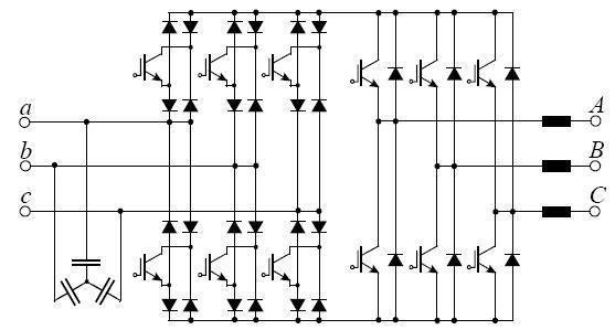
Sparse Matrix Converter
Characteristics of the Sparse Matrix Converter topology are 15 Transistors, 18 Diodes, and 7 Isolated Driver Potentials. Compared to the Direct matrix converter this topology provides identical functionality, but with a reduced number of power switches and the option of employing an improved zero DC-link current commutation scheme, which provides lower control complexity and higher safety and reliability.
Very Sparse Matrix Converter
Characteristics of the Very Sparse Matrix Converter topology are 12 Transistors, 30 Diodes, and 10 Isolated Driver Potentials. There are no limitations in functionality compared to the Direct Matrix Converter and Sparse Matrix Converter. Compared to the Sparse Matrix Converter there are fewer transistors but higher conduction losses due to the increased number of diodes in the conduction paths.
Ultra Sparse Matrix Converter
Characteristics of the Ultra Sparse Matrix Converter topology are 9 Transistors, 18 Diodes, and 7 Isolated Driver Potentials. The significant limitation of this converter topology compared to the Sparse Matrix Converter is the restriction of its maximal phase displacement between input voltage and input current which is restricted to ± 30°.
Multi-Step Commutation
This is a commutation scheme, depicted in Fig. 4. For a given switching state of the rectifier input stage, the commutation of the inverter output stage has to be performed in an identical manner to the commutation of a conventional voltage dc-link converter. The basic structure of the commutating bridge legs of the Sparse Matrix Converter is shown in Fig. 4(a). The switch sequence to change the connection of the positive dc-link voltage bus p from input a to input b is shown in Fig. 4(b) and Fig. 4(c). In Fig. 4(b) the assumption is current-independent commutation with uab > 0. In Fig. 4(c) the assumption is voltage-independent commutation with i > 0.
A dead time between the turn-off and turn-on of the power transistors of a bridge leg has to be implemented in order to avoid a short circuit of the dc-link voltage. To change the switching state of the Sparse Matrix Converter rectifier input stage for a given inverter switching state, one has to make sure that there is no bidirectional connection between any two input lines. This guarantees that no short-circuiting of an input line-to-line voltage can occur. Additionally a current path must be continuously provided. Therefore multistep commutation schemes, using voltage independent and current independent commutation as known for the Conventional Direct Matrix Converter , can be employed.
Zero DC Link Current Commutation
The drawback of the multistep commutation describe before is its complexity. Indirect matrix converters like the Sparse Matrix Converter provide a degree of control freedom that is not available for the Conventional Direct Matrix Converter. This can be used to simplify the complex commutation problem. It has been proposed to switch the inverter stage into a free-wheeling state, and then to commutate the rectifier stage with zero dc-link current. This is shown in Fig. 5.
Fig. 5(a) shows the control of the power transistors in one bridge leg of the Sparse Matrix Converter. Fig. 5(b) shows the switching state sequence where s0; s7 = 1 indicates free-wheeling operation of the inverter stage. Furthermore, the dc-link current i is shown.
The zero DC link current commutation scheme gives the additional benefit of a reduction in the switching losses of the input stage. One only has to ensure that no overlapping of turn-on intervals of power transistors in a bridge half occurs, because this would result in a short circuit of an input line-to-line voltage.
Fig 6 shows the formation of the dc-link voltage u and dc-link current i within one switching period Furthermore, it shows as an example the switching functions of the rectifier and inverter stage for