
Power type Electric Build date 1969-1970 | Model UCW 6E1 Total produced 20 | |
 | ||
Designer Union Carriage and Wagon Builder Union Carriage and Wagon | ||
The South African Railways Class 6E1, Series 1 of 1969 is an electric locomotive.
Contents
- Manufacturer
- Bogies
- Orientation
- Series identifying features
- Startup
- Running
- Brakes
- Service
- Cape Western network
- Northern network
- Illustration
- References
In 1969 and 1970, the South African Railways placed twenty Class 6E1, Series 1 electric locomotives with a Bo-Bo wheel arrangement in mainline service. Their limited number and the fact that they entered service before the Class 6E, suggest that the Class 6E1, Series 1 locomotives were obtained as demonstrators, before a decision was made on which of the two classes would be perpetuated.
Manufacturer
The 3 kV DC Class 6E1, Series 1 electric locomotive was designed and built for the South African Railways (SAR) in 1969 and 1970 by Union Carriage and Wagon (UCW) in Nigel, Transvaal, with the electrical equipment supplied by Associated Electrical Industries (AEI) and English Electric (EE).
Twenty locomotives were delivered in 1969 and 1970, numbered in the range from E1226 to E1245. UCW did not allocate builder’s or works numbers to the locomotives it built for the SAR and used the SAR unit numbers for their record keeping.
Bogies
The twenty Series 1 locomotives are identical to the Class 6E in all respects, including traction motors, power, tractive force and body dimensions. The only obvious visual distinguishing feature to tell the Class 6E1, Series 1 apart, was its new design bogies with their distinctive traction struts and linkages.
Together with the locomotive's electronic wheelslip detection system, these traction struts, mounted between the linkages on the bogies and the locomotive body and colloquially referred to as grasshopper legs, ensure the maximum transfer of power to the rails without causing wheel-slip, by reducing the adhesion of the leading bogie and increasing that of the trailing bogie by as much as 15% upon starting off. This feature was controlled by electronic wheel-slip detection devices and an electric weight transfer relay, which reduced the anchor current to the leading bogie by as much as 50A in notches 2 to 16. These grasshopper legs and linkages were to become a distinguishing feature on the bogies of most subsequent South African electric locomotive classes.
The limited number of Class 6E1, Series 1 locomotives which were placed in service and the fact that they entered service before the Class 6E, suggest that the Series 1 locomotives were obtained as demonstrators for these new bogies to be evaluated, before a decision was made about their continued production.
Orientation
These dual cab locomotives have a roof access ladder on one side only, just to the right of the cab access door. The roof access ladder end is marked as the no. 2 end. A corridor along the centre of the locomotive connects the cabs, which are identical, apart from the fact that the handbrake is located in cab 2. A pantograph hook stick is stowed in a tube, mounted below the lower edge of the locomotive body on the roof access ladder side. The locomotive has three small panels along the lower half of the body on the roof access ladder side, and only one panel on the opposite side.
Series identifying features
The Class 6E1 was produced in eleven series over a period of nearly sixteen years, with altogether 960 units placed in service, all built by UCW. This makes the Class 6E1 the most numerous single locomotive class ever to have seen service in South Africa and serves as ample proof of a highly successful design.
While some Class 6E1 series are visually indistinguishable from their predecessors or successors, some externally visible changes did occur over the years. Like the Classes 5E, 5E1 and 6E, the Class 6E1, Series 1 locomotives had their sandboxes mounted on the bogies, while all the subsequent series Class 6E1s had their sandboxes mounted along the bottom edge of the locomotive body, with the sandbox lids fitting into recesses in the body.
Startup
When there is no compressed air in the locomotive's system to raise a pantograph to start up, a pantograph hook stick is used to manually raise the pantograph. This starts the high voltage motor, which drives the auxiliary alternator to supply 110V power, to start the compressor and power other control circuits. Once there is enough main air pressure to keep the pantograph in the raised position, the pantograph hook stick can be dropped.
The locomotive is controlled via resistors, over which the voltage is dropped in a configuration of series and parallel electrical circuits. The circuit breakers which switch these circuits, work under very high power and voltage and are therefore all pneumatically operated for insulation purposes. Compressed air is required to open or close the switch actions and air is also used for the weakfield cam switch, which also switches under very high currents.
Running
Upon starting off and in the low notches, the major part of the voltage is dropped over the banks of resistors and all four traction motors are in series. The blowers which, accelerate the dissipation of heat in the resistor banks, give the Class 6E its very distinctive sound, a deep and loud whine when power is applied.
As the driver notches up, some of the resistor banks are cut out via the pneumatically operated switches and the voltage increases across the traction motors. The more resistors which are cut out as the driver notches higher, the more power is developed by the traction motors. At around 22 to 28 kilometres per hour (14 to 17 miles per hour) the locomotive switches to a parallel combination, where the two traction motors per bogie are in a series electrical circuit, while the two bogies are in parallel electrical circuit. Eventually, when all resistors are cut out, the locomotive is operating in full-field.
When the traction motors are operated in full-field, be it in series or parallel mode, they are performing at maximum power for normal operation. To increase the speed at this point, if necessary, higher power output is required from the traction motors. The only way to increase power is to force a higher current flow. To accomplish this, the weakfield cam switch switches resistance in parallel with the field coils, which reduces the overall resistance of the field coils. This increases the magnetic flux and more power is generated by the traction motors, over short periods.
Brakes
The locomotive itself used air brakes, but it was equipped to operate trains with air or vacuum brakes. The brake system would be set up for either air or vacuum train working by means of a turning switch on the driver's brake valve, and by pre-setting the appropriate brake valves in the passage.
The Class 6E1 locomotives were built with an air brake system, consisting of various valves connected to each other with pipes, commonly referred to as a “bicycle frame” brake system. The compressed air pipes run under the locomotive's belly in a zig-zag pattern, going through bolster and other members to extend its length, to allow the maximum amount of moisture to condense on the way to the reservoirs. As a result, it has multiple pipe connections. A weakness of the system was that, after an accident or even a hard coupling, these pipes tended to develop leaks at the joints, which were extremely difficult to repair.
While hauling a vacuum braked train, the locomotive's air brake system would be disabled and the train would be controlled by using the train brakes alone to slow down and stop. While hauling an air braked train, on the other hand, the locomotive brakes would engage along with the train brakes. While working either type of train downgrade, the locomotive's regenerative braking system would also work in conjunction with the train brakes.
Unlike the Classes 5E and 5E1, whose air brakes could be applied independently on each bogie when the locomotive was stopped, the air brakes on both bogies would be applied together on the Classes 6E and 6E1. The handbrake or parking brake, located in Cab no. 2, only operated on the unit's last axle, or no. 7 and 8 wheels.
Service
The Class 6E1 family saw service all over both of the 3 kV DC mainline and branchline networks.
Cape Western network
The smaller network is the Cape Western line between Cape Town and Beaufort West, with the locomotives based at the Bellville Depot in Cape Town.
Northern network
The larger network covers portions of the Northern Cape, the Free State, Natal, Gauteng, North West Province and Mpumalanga, the main routes in this vast area being as follows:
The electric locomotives, allocated to depots within this network, are largely pooled and can operate anywhere in the network, as required by the Operating Department, but they return to their home depots for maintenance every twenty-eight days.
In 2011, the Class 6E1 began to be withdrawn from the Natal corridor (NatCor) line between Johannesburg and Durban, and replaced with Class 18E locomotives.
In KwaZulu-Natal, the coastal sections from Durban to Empangeni in the north and to Port Shepstone in the south were due to be dieselised at the end of October 2011, using EMD Classes 34 and 37-000 locomotives, which were being displaced by the introduction of new Class 43-000 diesel-electric locomotives on the line from Mpumalanga via Swaziland to Richards Bay.
In practice, however, electric locomotives were observed at Port Shepstone as late as 24 May 2012, while the diesel power on the South Coast line consisted predomiminantly of Class 37-000 locomotives. The overhead catenary equipment between Stanger and Empangeni and between Kelso and Port Shepstone was to be removed soon after the end of October 2011, but actual removal only took place in November 2013. By October 2014, the catenary masts, sans wiring, were still standing at Port Shepstone.
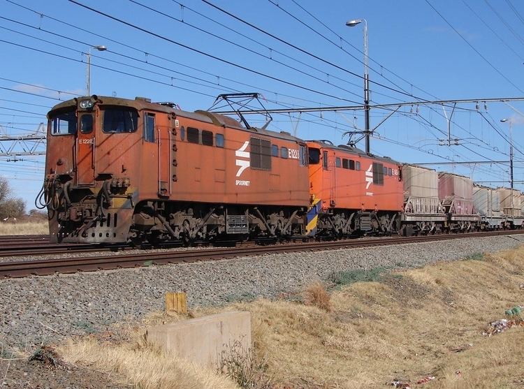
Illustration
The Series 1 locomotives were all delivered in the SAR Gulf Red livery with yellow whiskers. By c. 2000, they were all repainted in the Spoornet orange livery.