
 | ||
A solar turbine power plant uses the energy in solar radiation captured by so-called solar collectors. Solar power is a renewable source of energy. The solar radiant energy reaching the earth's surface is around 1.783*1014 KJ or 1.353kJ/s per square meter. Solar power plants, such as the Blythe Solar Power Project, operate mainly on closed power cycles: Rankine cycles (for low temperature ranges) and Brayton cycles (for high temperature ranges). Solar plants provide energy ranging from a few kilowatts to a few megawatts. The constraints associated with solar plants are size, space, high capital cost, and the inevitable fluctuations in the daily supply of solar radiant energy.
Contents
- Concentration ratio
- Optical efficiency
- Collector efficiency
- Solar receiver
- External receivers
- Cavity receivers
- Tubular receivers
- Distributed receiver system
- Central receiver system
- Net efficiency
- Solar energy storage
- Solar turbines
- Coolants and working fluids
- Steam turbines
- Gas turbine
- Advantages
- Disadvantages
- References
Concentration ratio
The concentration ratio is the ratio of the area of the concentrator to the area of the receiver surface. The amount of solar energy incident on the concentrator is directed towards the receiver, so the ratio is a measure of the energy concentrated towards the receiver.
Higher concentration ratio values can be attained by using large apertures and small receiver. Receiver temperature increases with the increase in concentration ratio, as shown in Figure 2. Concentration ratios vary from 1.5 to 3000 depending on the type of collector, i.e., whether it is a medium- or high-temperature collector. This is an important parameter in determining the efficiency of a solar plant.
Optical efficiency
The optical efficiency of a solar collector relates the percentage of the solar rays penetrating the transparent cover of the collector (transmission) and the percentage being absorbed.
Where
Therefore,
Collector efficiency
There are three types of solar collectors: low (100 °C), medium (300-400 °C), and high (400-700 °C) temperature collectors. Each type has its own efficiency.
The losses can be expressed by the overall co-efficient
where TR is the receiver temperature ratio. TR increases with the concentration ratio, as shown in Figure 2. Collector efficiency decreases with the temperature ratio, as shown in Figure 3.
Solar receiver
The receiver absorbs heat transmitted by the collector. Sometimes the receiver is an integral part of the system, for example, in solar ponds and flat plate collectors. Receivers may be stationary or portable.
There are three types of receivers: external, tubular, and cavity.
External receivers
A working fluid is provided on the external surface of a vertical body (Figure 4).
Major losses are due to:
Concentration ratio and fluid temperature attained are 1000 and 500 °C, respectively.
Cavity receivers
Heat flux enters through the apertures as shown in Figure 5; concentrators transmit the heat flux to the surface of coolant tubes through the apertures. Heat energy is transferred to other parts (where the direct beam is unable to reach) through internal reflection. Overall size is large due to the number of coolant tubes.
Tubular receivers
This consists of a row of coaxial tubes. The outer tube receives the radiation, whereas the working fluid enters through the inner tube and leaves through the annular space between the tubes (Figure 6). Concentration ratio and maximum fluid temperature attained are around 1.5 and 200 °C, respectively.
Distributed receiver system
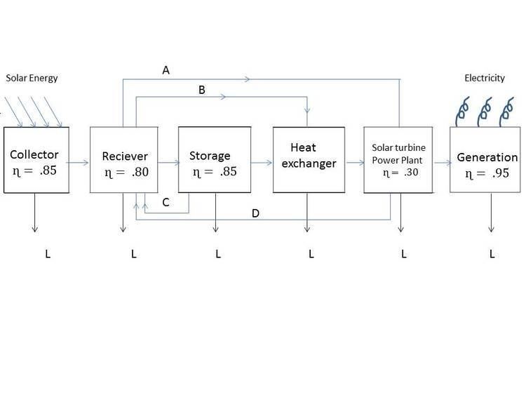
In this system the three collectors (as shown in Figure 7) collect the heat flux and transfer it to receiver from where the coolant takes this energy to the heat exchanger (Path A). The coolant at times serves the purpose of working fluid, as depicted by Path B.
Central receiver system
In this system, the solar collectors transmit the heat flux to a receiver which is large in size. External and cavity types of receivers can be employed for this purpose. Example: heliostats.
Net efficiency
The collector efficiency (ɳc) decreases with increases in receiver temperature. The thermal efficiency (ɳth) increases with increases in the inlet temperature of the working fluid. Therefore, overall plant efficiency (ɳn) varies, as shown in Figure 8. The net efficiency is between 15% and 20%. The curve is flat at maximum efficiency.
Solar energy storage
Since solar radiation is not always available, it becomes necessary to store the energy in some form. Solar thermal energy storage can be done in:
- Solids: Some rocks absorb heat. The amount of energy stored depends on the mass of the solid material, its specific heat, and the allowable temperature rise.
- Liquids: If the heat is stored below the boiling point of fluids at ambient pressure then some fluids can be used as heat storage media. Some liquids which can be used for this purpose are Sodium, Hitec, Therminol, and oils.
- Latent heat of fusion: In this type of system a solid is heated until it melts. Thus heat is stored in the body at constant temperature in the form of latent heat. Examples LiF (latent heat = 1050 kJ/Kg melting point = 848 °C) and LiOH (latent heat = 1080 kJ/Kg melting point =471 °C).
- A combination of any of the above approaches can also be used to store solar energy.
Solar turbines
The performance of the coolants, working fluid, and steam or gas turbines together determine the efficiency of the plant.
Coolants and working fluids
A coolant absorbs energy in the receiver and transfers the energy to the working fluid in the heat exchanger. Example water/steam, liquid metals, molten salts, gases and oils.
Water can be used as coolants in low and medium temperature solar power plants.
The maximum temperature deployed in an oil type of coolant is 250 °C. Oil can be dangerous because it is flammable. It is also relatively costly.
Gases that can be used as coolants are air, helium, argon, and carbon dioxide. They can be used for high temperature ranges (Tmax=800 °C).
Molten salts are also used for high temperature regions. They have high specific heat.
Molten metals (sodium or aluminium) can also be used as coolants. Since their density is high they require a smaller receiver.
steam, freon, or helium are some of gases used as working fluids.
Steam turbines
Steam turbines operate on a Rankine cycle. Steam can be generated by a receiver directly from the solar heat flux, which eliminates the need for a heat exchanger. However, some plants deploy molten salts to attain higher temperatures, which eliminates the need for steam boilers. Values of pressure and temperature in solar plants are 50-100 bar and 400-500 °C, respectively. Both impulse and reaction stages can be used. For small values of power, impulse stages are preferable.
Gas turbine
Gas turbines operate on a Brayton cycle, that is, with inlet temperatures around 500-800 °C. A conventional gas turbine power plant uses a combustion chamber, but here the combustion chamber is the receiver/heat exchanger. However, using a gas solar turbine power plants with stored thermal energy is quite difficult because the power plant operates at a high temperature range and it is quite difficult to store heat energy at this high temperature. Gas turbines use fewer stages, do not require feed water heaters or condensers and have a low cooling requirement.