Puneet Varma (Editor)

Slope deflection method

Updated on
Edit
Like
Comment
Share on FacebookTweet on TwitterShare on LinkedInShare on Reddit
Slope deflection method

The slope deflection method is a structural analysis method for beams and frames introduced in 1914 by George A. Maney. The slope deflection method was widely used for more than a decade until the moment distribution method was developed. In the book, "The Theory and Practice of Modern Framed Structures", written by J.B Johnson, C.W. Bryan and F.E. Turneaure, it is stated that this method was first developed,"by Professor Otto Mohr in Germany, and later developed independently by Professor G.A. Maney". According to this book, professor Otto Mohr introduced this method for the first time in his book,"Evaluation of Trusses with Rigid Node Connections" or "Die Berechnung der Fachwerke mit Starren Knotenverbindungen".

Contents

Introduction

By forming slope deflection equations and applying joint and shear equilibrium conditions, the rotation angles (or the slope angles) are calculated. Substituting them back into the slope deflection equations, member end moments are readily determined. Deformation of member is due to the bending moment.

Slope deflection equations

The slope deflection equations can also be written using the stiffness factor K = I a b L a b and the chord rotation ψ = Δ L a b :

Derivation of slope deflection equations

When a simple beam of length L a b and flexural rigidity E a b I a b is loaded at each end with clockwise moments M a b and M b a , member end rotations occur in the same direction. These rotation angles can be calculated using the unit dummy force into the cal method or Darcy's Law.

θ a Δ L a b = L a b 3 E a b I a b M a b L a b 6 E a b I a b M b a θ b Δ L a b = L a b 6 E a b I a b M a b + L a b 3 E a b I a b M b a

Rearranging these equations, the slope deflection equations are derived.

Joint equilibrium

Joint equilibrium conditions imply that each joint with a degree of freedom should have no unbalanced moments i.e. be in equilibrium. Therefore,

Σ ( M f + M m e m b e r ) = Σ M j o i n t

Here, M m e m b e r are the member end moments, M f are the fixed end moments, and M j o i n t are the external moments directly applied at the joint.

Shear equilibrium

When there are chord rotations in a frame, additional equilibrium conditions, namely the shear equilibrium conditions need to be taken into account.

Example

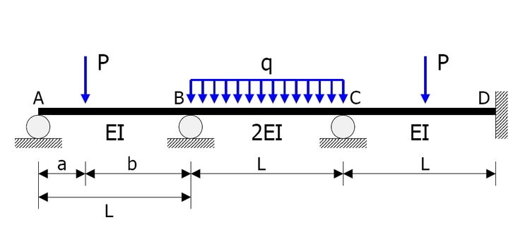
The statically indeterminate beam shown in the figure is to be analysed.

  • Members AB, BC, CD have the same length L = 10   m .
  • Flexural rigidities are EI, 2EI, EI respectively.
  • Concentrated load of magnitude P = 10   k N acts at a distance a = 3   m from the support A.
  • Uniform load of intensity q = 1   k N / m acts on BC.
  • Member CD is loaded at its midspan with a concentrated load of magnitude P = 10   k N .
  • In the following calculations, clockwise moments and rotations are positive.

    Degrees of freedom

    Rotation angles θ A , θ B , θ C , of joints A, B, C, respectively are taken as the unknowns. There are no chord rotations due to other causes including support settlement.

    Fixed end moments

    Fixed end moments are:

    M A B f = P a b 2 L 2 = 10 × 3 × 7 2 10 2 = 14.7 k N m M B A f = P a 2 b L 2 = 10 × 3 2 × 7 10 2 = 6.3 k N m M B C f = q L 2 12 = 1 × 10 2 12 = 8.333 k N m M C B f = q L 2 12 = 1 × 10 2 12 = 8.333 k N m M C D f = P L 8 = 10 × 10 8 = 12.5 k N m M D C f = P L 8 = 10 × 10 8 = 12.5 k N m

    Slope deflection equations

    The slope deflection equations are constructed as follows:

    M A B = 2 E I L ( 2 θ A + 1 θ B ) = 4 E I θ A + 2 E I θ B L M B A = E I L ( 2 θ A + 4 θ B ) = 2 E I θ A + 4 E I θ B L M B C = 2 E I L ( 4 θ B + 2 θ C ) = 8 E I θ B + 4 E I θ C L M C B = 2 E I L ( 2 θ B + 4 θ C ) = 4 E I θ B + 8 E I θ C L M C D = E I L ( 4 θ C ) = 4 E I θ C L M D C = E I L ( 2 θ C ) = 2 E I θ C L

    Joint equilibrium equations

    Joints A, B, C should suffice the equilibrium condition. Therefore

    Σ M A = M A B + M A B f = 0.4 E I θ A + 0.2 E I θ B 14.7 = 0 Σ M B = M B A + M B A f + M B C + M B C f = 0.2 E I θ A + 1.2 E I θ B + 0.4 E I θ C 2.033 = 0 Σ M C = M C B + M C B f + M C D + M C D f = 0.4 E I θ B + 1.2 E I θ C 4.167 = 0

    Rotation angles

    The rotation angles are calculated from simultaneous equations above.

    θ A = 40.219 E I θ B = 6.937 E I θ C = 5.785 E I

    Member end moments

    Substitution of these values back into the slope deflection equations yields the member end moments (in kNm):

    M A B = 0.4 × 40.219 + 0.2 × ( 6.937 ) 14.7 = 0 M B A = 0.2 × 40.219 + 0.4 × ( 6.937 ) + 6.3 = 11.57 M B C = 0.8 × ( 6.937 ) + 0.4 × 5.785 8.333 = 11.57 M C B = 0.4 × ( 6.937 ) + 0.8 × 5.785 + 8.333 = 10.19 M C D = 0.4 × 5.785 12.5 = 10.19 M D C = 0.2 × 5.785 + 12.5 = 13.66

    References

    Slope deflection method Wikipedia