
 | ||
Seismic refraction is a geophysical principle (see refraction) governed by Snell's Law. Used in the fields of engineering geology, geotechnical engineering and exploration geophysics, seismic refraction traverses (seismic lines) are performed using a seismograph(s) and/or geophone(s), in an array and an energy source. The seismic refraction method utilizes the refraction of seismic waves on geologic layers and rock/soil units in order to characterize the subsurface geologic conditions and geologic structure.
Contents
- P Wave Refraction aka Compression Wave Refraction
- S Wave Refraction aka Shear Wave Refraction
- Two Horizontal Layers
- Inversion methods
- References
The methods depend on the fact that seismic waves have differing velocities in different types of soil (or rock): in addition, the waves are refracted when they cross the boundary between different types (or conditions) of soil or rock. The methods enable the general soil types and the approximate depth to strata boundaries, or to bedrock, to be determined.
P-Wave Refraction (a.k.a. Compression Wave Refraction)
P-wave refraction evaluates the compression wave generated by the seismic source located at a known distance from the array. The wave is generated by vertically striking a striker plate with a sledgehammer, shooting a seismic shotgun into the ground, or detonating an explosive charge in the ground. Since the compression wave is the fastest of the seismic waves, it is sometimes referred to as the primary wave and is usually more-readily identifiable within the seismic recording as compared to the other seismic waves.
S-Wave Refraction (a.k.a. Shear Wave Refraction)
S-wave refraction evaluates the shear wave generated by the seismic source located at a known distance from the array. The wave is generated by horizontally striking an object on the ground surface to induce the shear wave. Since the shear wave is the second fastest wave, it is sometimes referred to as the secondary wave. When compared to the compression wave, the shear wave is approximately one-half (but may vary significantly from this estimate) the velocity depending on the medium.
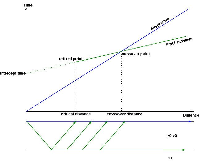
Two Horizontal Layers.
ic0 - critical angle
V0 - velocity of the first layer
V1 - velocity of the second layer
h0 - thickness of the first layer
T01 - intercept