
 | ||
A rotor wing is a lifting rotor or wing which spins to provide aerodynamic lift. In general, a rotor may spin about an axis which is aligned substantially vertically, fore-and aft, or side to side (spanwise). All three classes have been studied for use as lifting rotors, although only vertical-axis rotorcraft such as the helicopter have come into common use.
Contents
- Classification
- Conventional rotors
- Stopped rotors
- Magnus rotors
- Flettner rotor
- Cross flow fan
- Radial lift rotors
- References
Some types provide lift at zero forward airspeed, allowing for vertical takeoff and landing (VTOL), as in the helicopter. Others require forward airspeed in the same manner as a fixed-wing aircraft. Many can also provide forward thrust if required.
Classification
Classes of rotor wing include:
Conventional rotors
Conventional rotorcraft have vertical-axis rotors. The main types include the helicopter with powered rotors providing both lift and thrust, and the autogyro with unpowered rotors providing lift only. There are also various hybrid types.
Stopped rotors
Some rotor wing aircraft are designed to stop the rotor for forward flight, so that it then acts as a fixed wing to provide some or all of the lift required. For vertical flight and hovering it spins to act as a rotary wing or rotor, and for forward flight at speed it stops to act as a fixed wing. Additional fixed wings may also be provided to help with stability and control and to provide auxiliary lift.
An early American proposal was the conversion of the Lockheed F-104 Starfighter with a triangular rotor wing. The idea was later revisited by Hughes. The Sikorsky S-72 research aircraft underwent extensive flight testing.
The later canard rotor/wing (CRW) concept added a "canard" foreplane as well as a conventional tailplane, offloading the rotor wing and providing control during forward flight. For vertical and low-speed flight, the main airfoil is tip-driven as a helicopter's rotor by exhaust from a jet engine, and there is no need for a tail rotor. In high-speed flight the airfoil is stopped in a spanwise position, as the main wing of a three-surface aircraft, and the engine exhausts through an ordinary jet nozzle. Two Boeing X-50 Dragonfly prototypes were flown from 2003 but the program ended after both had crashed, having failed to transition successfully.
In 2013 the US Naval Research Laboratory (NRL) published a vertical-to-horizontal flight transition method and associated technology, said to be patented, which they call the Stop-Rotor Rotary Wing Aircraft. The Australian company StopRotor Technology Pty Ltd has developed a prototype Hybrid RotorWing (HRW) craft. The design uses high alpha airflow to provide a symmetrical airflow across all the rotor blades, requiring it to drop almost vertically during transition. Inflight transition from fixed to rotary mode was demonstrated in August 2013.
Another approach proposes a tailsitter configuration in which the lifting surfaces act as a rotors during takeoff, the craft tilts over for horizontal flight and the rotor stops to act as a fixed wing.
Magnus rotors
When a spinning body passes through air at right angles to its axis of spin, it experiences a sideways force in the third dimension. This Magnus effect was first demonstrated on a spinning cylinder by Gustav Magnus in 1872. If the cylinder axis is aligned spanwise (side to side) then forward movement through the air generates lift. The rotating body does not need to be a cylinder and many related shapes have been studied.
Flettner rotor
The Flettner rotor comprises a Magnus cylinder with a disc endplate at each end. The American Plymouth A-A-2004 floatplane had Flettner rotors in place of the main wings and achieved short flights in 1924.
Cross-flow fan
The cross-flow fan comprises a radial arrangement of blades around a central axis, which is placed in a shaped duct. Rotating the fan causes air to be drawn in at one end of the duct, passed through the fan and expelled at the other end. The FanWing is a lifting rotor which uses this principle to augment lift, even at very low airspeeds, by drawing air downwards. A prototype UAV was flown in 2007.
Radial-lift rotors
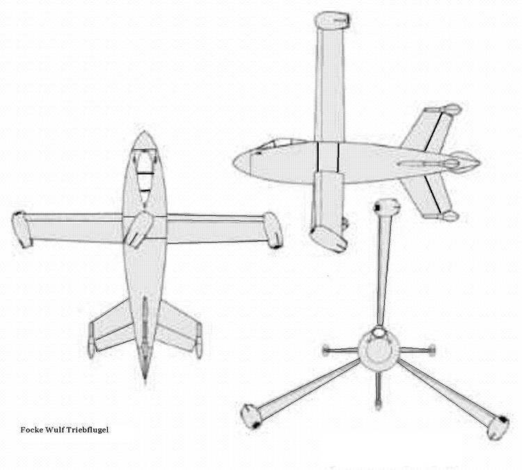
During World War II Focke-Wulf proposed the Triebflügel, in which a tipjet-driven rotor wing is located around the fuselage waist. The proposed mode of operation was to land and take off as a tail-sitter, using the wing as a rotor. The craft would then tilt over to conventional horizontal flight and lift would be provided by cyclic pitch variation of the rotor wings, with the wing tip ramjets now angled to provide thrust.
A few years later the American Vought XF5U circular-winged fighter prototype was designed with large radial-lift propellers. These were angled upwards when the craft was on the ground, creating a cyclic variation in the blades' angle of attack or pitch when the craft was moving forwards. This cyclic variation induced a radial lifting component to the blades, when in the horizontal segment of rotation, which was intended to augment the wing lift. A prototype aircraft was completed but the project was closed before the prototype had flown.