
 | ||
The Richards controller is a method of implementing a finite state machine using simple integrated circuits and combinational logic. The method has been named after its inventor, Charles L. Richards. One of the distinct advantages of this method over conventional finite state machine design methods is that it allows for easier design of complex finite state machines than the traditional techniques of state diagrams, state transition tables and Boolean algebra offer. Using Richards technique, it becomes relatively easy to implement machines with many hundreds or even thousands of states.
Contents
History
The Richards controller was made because of the need for an easier method of designing finite state machines than using the traditional method of state diagrams, state transition tables, and logic minimization. At the time many of the computer based logic minimization tools that we have today did not exist. Hence logic minimization was for the most part limited to the use of Karnaugh Maps and DeMorgan's Law. Because of this Charles L. Richards invented a method of implementing a finite state machine that did not need an explicit state transition table. He published his findings in the February 1973 issue of Electronics. His generalized implementation became popular and by the 1980s was considered a classic design method. While it is unlikely that commercial products found today contain a classic Richards controller, (since there are faster designs now than ones that use loadable counters,) there is a good chance of a modified Richards controller or a design derived from the Richards controller being used.
Applications
Because of the Richards controller's ability to scale to use many states easily, it can be used in many practical applications.
The Richards flowchart
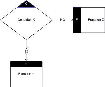
The Richards controller is a Mealy machine since its output is dependent on both the current state and the input. However Richards designed his own method of representing states using a flowchart diagram, instead of the state diagram. Each state is represented as a transfer condition on the flowchart. Each condition has two control paths leading out of it, a YES or a NO. The condition is YES or NO (TRUE or FALSE) based upon a single bit input to the machine. (Richards p. 108) Depending on what the input for a condition is, one of the two transfer functions associated with that condition will be executed. The machine considers executing a function to be setting the output of a single pin on the device, this can be used to trigger combinational logic. After a transfer function is executed, the machine will enter a new state, each transfer function will either implicitly or explicitly define a new state to transition to. An implicit state definition could also be called the default, since it will occur without any additional circuitry from the designer, if the condition is YES then it will transition to the next state numerically. For example, if you are at state 0 and a YES occurs then you will transition to state 1. If the condition is NO, then the machine will remain at its current state. Using this behavior it is possible to create a machine with a simple sequential flowchart. Of course a sequential machine is usually not very useful, thankfully there is a way to transition to states out of order, using a so-called jump. To implement a jump requires additional hardware to select the destination state. The exact hardware depends on the function being executed.
Kernel of the controller
The Richards controller's core kernel can be boiled down into four parts, a counter, a multiplexer, and two decoders. A simple controller can be built using the classic 7400 series of TTL logic integrated circuits. The counter used is the 74163, the multiplexer is the 74151 and the two decoders are the 7442 part. (Richards, p. 108) The output from the counter selects what bit from the multiplexer input should be sent to the output Y, (the inverse of which is sent to the output WN.) If Y is high, then the counter is allowed to increment, otherwise it is not. Likewise, Y must be high to enable YES function outputs since the D input on the decoder is connected to WN, while it must be low to enable the NO function outputs, since the D input on that decoder is set to Y. To perform a jump, you must set the LDN bit on the counter, and the A, B, C and D inputs. LDN tells the counter to load the value on the A, B, C and D inputs. Using some combinational logic, you can load a value into the counter for certain functions but not others, as well as specifying the state address to be loaded, given what function is active. Doing this is a simple matter of building a table of functions and the states that they should transition to, then finding the Boolean Algebra expression for each bit that makes up the address of the state to be jumped to.