
 | ||
A Registered Jack (RJ) is a standardized telecommunication network interface for connecting voice and data equipment to a service provided by a local exchange carrier or long distance carrier. Registration interfaces were first defined in the Universal Service Ordering Code (USOC) system of the Bell System in the United States for complying with the registration program for customer-supplied telephone equipment mandated by the Federal Communications Commission (FCC) in the 1970s. They were subsequently codified in the Code of Federal Regulations Part 68.
Contents
- Naming standard
- History and authority
- Registered jack types
- Unofficial plug names
- International use
- RJ11 RJ14 RJ25 wiring
- Pinouts
- Provisioning of power
- RJ21
- Similar connectors
- RJ45S
- RJ48
- RJ61
- References
The specification includes physical construction, wiring, and signal semantics. Accordingly, registered jacks are primarily named by the letters RJ, followed by two digits that express the type. Additionally, letter suffixes indicate minor variations. For example, RJ11, RJ14, and RJ25 are the most commonly used interfaces for telephone connections for one-, two-, and three-line service, respectively. Although these standards are legal definitions in the United States, some interfaces are used world-wide.
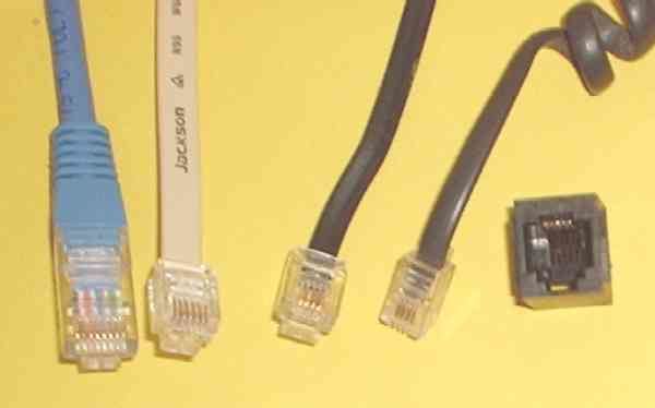
The connectors used for registered jack installations are primarily the modular connector and the 50-pin miniature ribbon connector types. For example, RJ11 uses a six-position two-conductor connector (6P2C), RJ14 uses a six-position four-conductor (6P4C) modular jack, while RJ21 uses a 25-pair (50-pin) miniature ribbon connector.
Naming standard
The registered jack designations originated in the standardization processes in the Bell System in the United States, and describe application circuits and not just the physical geometry of the connectors; inspection of the connector does not necessarily show which registered jack wiring is used. The same modular connector type may be used for different registered jack applications.
Strictly, Registered Jack refers to both the female physical connector (modular connector) and its wiring, but the term is often used loosely to refer to modular connectors regardless of wiring or gender, such as in Ethernet over twisted pair. There is much confusion over these connection standards. The same six-position plug and jack commonly used for telephone line connections may be used for RJ11, RJ14 or even RJ25, all of which are names of interface standards that use this physical connector. The RJ11 standard dictates a single wire pair connection, while RJ14 is a configuration for two lines, and RJ25 uses all six wires for three telephones lines. The RJ designations, though, only pertain to the wiring of the jack, hence the name Registered Jack; it is commonplace, but not strictly correct, to refer to an unwired plug by any of these names.
Modular connectors were developed to replace older telephone installation methods that used either hardwired cords, or bulkier varieties of telephone plugs. The common nomenclature for modular connectors includes the number of contact positions and the number of wires connected, for example 6P indicates a six-position modular plug or jack. A six-position modular plug with conductors in the middle two positions and the other four positions unused has the designation 6P2C. RJ11 uses a 6P2C connector. The connectors could be supplied with more pins, but if more pins are actually wired, the interface is not an RJ11.
History and authority
Registration interfaces were created by the Bell System under a 1976 Federal Communications Commission order for the standard interconnection between telephone company equipment and customer premises equipment. These interfaces used newly standardized jacks and plugs, primarily based on miniature modular connectors.
The wired communications provider (telephone company) is responsible for delivery of services to a minimum (or main) point of entry (MPOE). The MPOE is a utility box, usually containing surge protective circuitry, which connects the wiring on the customer's property to the communication provider's network. Customers are responsible for all jacks, wiring, and equipment on their side of the MPOE. The intent was to establish a universal standard for wiring and interfaces, and to separate ownership of in-home (or in-office) telephone wiring from the wiring owned by the service provider.
In the Bell System, following the Communications Act of 1934, the telephone companies owned all telecommunications equipment and they did not allow interconnection of third-party equipment. Telephones were generally hardwired, but may have been installed with Bell System connectors to permit portability. The legal case Hush-A-Phone v. United States (1956) and the Federal Communications Commission's (FCC) Carterfone (1968) decision brought changes to this policy, and required the Bell System to allow some interconnection, culminating in the development of registered interfaces using new types of miniature connectors.
Registered jacks replaced the use of protective couplers provided exclusively by the telephone company. The new modular connectors were much smaller and cheaper to produce than the earlier, bulkier connectors that were used in the Bell System since the 1930s. The Bell System issued specifications for the modular connectors and their wiring as Universal Service Order Codes (USOC), which were the only standards at the time. USOCs are commonly specified to the communications provider by large businesses for a variety of services. Because there are many standardized interface options available to the customer, the customer must specify the type of interface required by RJ/USOC. For a multi-line interface such as the RJ21 (which provided 25 pairs), the customer must denote which position(s) of the interface are to be used. If there are multiple RJ21 connectors, they are numbered sequentially and the customer must advise the communications provider of which one to use.
When the US telephone industry was opened to more competition in the 1980s, the specifications became US law, ordered by the FCC and codified in the Code of Federal Regulations (CFR), Title 47 CFR Part 68, Subpart F, superseded by T1.TR5-1999.
In January 2001, the FCC delegated responsibility for standardizing connections to the telephone network to a new private industry organization, the Administrative Council for Terminal Attachments (ACTA). The FCC removed Subpart F from the CFR and added Subpart G, which delegates the task to the ACTA. The ACTA generates its recommendations for terminal attachments from the standards published by the engineering committees of the Telecommunications Industry Association (TIA). ACTA and TIA jointly published a standard called TIA/EIA-IS-968 which contained the information that was formerly in the CFR.
The current version of that standard, called TIA-968-A, specifies the modular connectors at length, but not the wiring. Instead, TIA-968-A incorporates a standard called T1.TR5-1999, "Network and Customer Installation Interface Connector Wiring Configuration Catalog", by reference to specify the wiring. With the publication of TIA-968-B, the connector descriptions have been moved to TIA-1096-A. Note that a registered jack name such as RJ11 identifies both the physical connectors and the wiring (pinout) of it (see above).
Registered jack types
The most commonly recognized registered jack is the RJ11. This is a modular connector wired for one telephone line, using the center two contacts of six available positions, and is used for single-line telephones in homes and offices in most countries. RJ14 is similar to RJ11 but is wired for two lines and RJ25 has three lines. RJ61 is a similar registered jack for four lines.
The RJ45(S) jack is rarely used, but the designation RJ45 commonly refers to any 8P8C modular connector for application in computer networking (Ethernet).
The officially recognized types of registered jacks are listed in the following table:
Many of the basic names have suffixes that indicate subtypes:
For example, RJ11 comes in two forms: RJ11W is a jack from which a wall telephone can be hung, while RJ11C is a jack designed to have a cord plugged into it. (A cord can be plugged into an RJ11W as well.)
Unofficial plug names
The following RJ-style names do not refer to official ACTA types:
International use
The modular jack was chosen as a candidate for ISDN systems. In order to be considered, the connector system had to be defined under international standards. In turn this led to ISO 8877. Under the rules of the IEEE 802 standards project, international standards are to be preferred over national standards so the modular connector was chosen for IEEE 802.3i-1990, the original 10BASE-T twisted-pair wiring version of Ethernet.
RJ11, RJ14, RJ25 wiring
All of these registered jacks are described as containing a number of potential contact positions and the actual number of contacts installed within these positions. RJ11, RJ14, and RJ25 all use the same six-position modular connector, thus are physically identical except for the different number of contacts (two, four and six respectively) allowing connections for one, two, or three telephone lines respectively.
Cords connecting to an RJ11 interface require a 6P2C connector. Nevertheless, cords sold as RJ11 often use 6P4C connectors (six position, four conductor) with four wires. Two of the six possible contact positions connect tip and ring, and the other two conductors are unused.
The conductors other than the two central tip and ring conductors are in practice variously used for a second or third telephone line, a ground for selective ringers, low-voltage power for a dial light, or for anti-tinkle circuitry to prevent pulse dialing phones from sounding the bell on other extensions.
Pinouts
Observing the male connector from the cable opening, with prong facing downward, the pins are numbered 1–6, left to right:
However, with German domestic telephone equipment (and that in some neighboring countries), 6P4C plugs and sockets are typically only used to connect the telephone cable to the phone base unit, whereas the mechanically different TAE plug is used at the other end of the cable. Older base units may accommodate the additional connectors of TAE (E, W, a2, b2) and may feature non-RJ standard sockets that can be connected "straight“ to TAE plugs. Further, flat DIN 47100 cables typically place the wires in ascending order.
Provisioning of power
Some telephones such as the Western Electric Princess and Trimline telephone models required additional power (~6 V AC) for operation of the incandescent dial light. This power was delivered to the telephone set from a transformer by the second wire pair (pins 2 and 5) of the 6P4C connector.
RJ21
RJ21 is a registered jack standard for a modular connector using 50 conductors, usually used to implement a 25-line (or less) telephone connection such as that used in the 1A2 key telephone system. It is also known as a 50-pin telco connector, CHAMP(AMP) or an Amphenol connector (the latter is a genericized trademark, as Amphenol was the largest manufacturer of these at one time).
A cable color scheme, in common use, is determined for 25 pairs of conductors as follows: For each ring, the primary, more prominent color is chosen from {blue, orange, green, brown, slate}, in that order, and the secondary, thinner stripe color from {white, red, black, yellow, violet}, in that order. The tip conductor color scheme uses the same colors as the matching ring but switches the thickness of the primary and secondary colored stripes. Since the sets are ordered, an orange (color 2 in its set) with a yellow (color 4) is the color scheme for the 4·5 + 2 − 5 = 17th pair of wires. If the yellow is the more prominent, thicker stripe, then the wire is a tip conductor connecting to the pin numbered 25 + the pair #, which is pin 42 in this case. (Ring conductors connect to the same pin number as the pair number.)
A conventional enumeration of wire color pairs then begins blue (and white), orange (and white), green (and white) and brown (and white), which subsumes a color-coding convention used in cables of 4 or fewer pairs (8 wires or less) with 8P and 6P connectors.
Dual RJ21 connectors are often used on punch blocks to make a breakout box for PBX and other key telephone systems.
Similar connectors
The same physical connector is used to connect Ethernet ports in bulk from a switch with 50-pin ports to a CAT-5 rated patch panel, or between two patch panels. A cable with a 50-pin connector on one end can support 6 fully wired 8P8C connectors or Ethernet ports on a patch panel with 1 spare pair. Alternatively, only the necessary pairs for 10/100 Ethernet can be wired allowing 12 Ethernet ports with a single spare pair.
The same connector with spring bail locks is used for SCSI-1 connections. Some computer printers use a shorter 36-pin version known as a Centronics connector.
RJ45S
The RJ45S, a standard jack once specified for modem or data interfaces, uses a mechanically-keyed variation of the 8P8C body with an extra tab that prevents it from mating with other connectors; the visual difference from the more-common 8P8C is subtle. The original RJ45S keyed 8P2C modular connector had pins 5 and 4 wired for tip and ring of a single telephone line, and pins 7 and 8 shorting a programming resistor, but is obsolete today.
RJ48
RJ48 is a registered jack. It is used for T1 and ISDN termination and local area data channels/subrate digital services. It uses the eight-position modular connector (8P8C).
RJ48C is commonly used for T1 circuits and uses pin numbers 1, 2, 4 and 5.
RJ48X is a variation of RJ48C that contains shorting blocks in the jack so that a loopback is created for troubleshooting when unplugged by connecting pins 1 and 4, and 2 and 5. Sometimes this is referred to as a self-looping jack.
RJ48S is typically used for local area data channels and subrate digital services, and carries one or two lines. It uses a keyed variety of the 8P8C modular connector.
RJ48 connectors are fastened to shielded twisted pair (STP) cables, not the standard unshielded twisted pair (UTP) CAT-(1-5).
RJ61
RJ61 is a physical interface often used for terminating twisted pair type cables. It uses an eight position, eight conductor (8P8C) modular connector.
This pinout is for multi-line telephone use only; RJ61 is unsuitable for use with high-speed data, because the pins for pairs 3 and 4 are too widely spaced for high signaling frequencies. T1 lines use another wiring for the same connector, designated RJ48. Ethernet over twisted pair (10BASE-T, 100BASE-TX and 1000BASE-T) also use a different wiring for the same connector, either T568A or T568B. RJ48, T568A, and T568B are all designed to keep pins close together for pairs 3 and 4.
The flat eight-conductor silver-satin cable traditionally used with four-line analog telephones and RJ61 jacks is also unsuitable for use with high-speed data. Twisted pair cabling must be used with RJ48, T568A and T568B. Twisted-pair data patch cable used with the three data standards above is not a direct replacement for RJ61 cable, because RJ61 pairs 3 and 4 would be split among different patch cable twisted pairs, causing cross-talk between voice lines 3 and 4 that might be noticeable for long patch cables.
With the advent of structured wiring systems and TIA/EIA-568-B conventions, the RJ61 pinout is falling into disuse. The T568A and T568B standards are used in place of RJ61 so that a single wiring standard in a facility can be used for both voice and data.