
 | ||
Recreational vehicles (RV) are designed to be truly self-contained so a refrigerator is an essential appliance. RVs are subject to conditions that make the design of their refrigerators challenging. The main challenges are vehicle vibration, accelerations, the energy required to drive the refrigeration process, and the off-level nature of vehicles. The absorption type refrigerator overcomes most of these design challenges and this is why the absorption refrigerator has been popular since the 1950s.
Contents
Overview
Following is a block diagram and a simplified drawing of a typical absorption type RV Fridge. The block diagram is a simplification of the fridge cycle which shows the key components combined with the fluid flow within the circuit. The simplified fluids schematic more closely resembles the actual refrigeration cycle so that the reader can draw a connection between the components on their fridge and what is occurring within the cooling unit pressure vessel.
Brief history of absorption refrigeration
The first absorption refrigeration system was patented by Ferdinand Carre in 1859. This refrigeration system had mechanical pumps and throttling valves which change the pressures in the refrigeration cycle.
The RV Fridge is considered a single pressure absorption refrigeration (SPAR) system because the entire system is at the same total pressure. Because there are no pumps or compressors it is easy to sustain these fridges in an RV as long as propane (LP gas) is available. The SPAR was patented by Baltzar von Platen and Carl Munters in 1923.
Block diagram
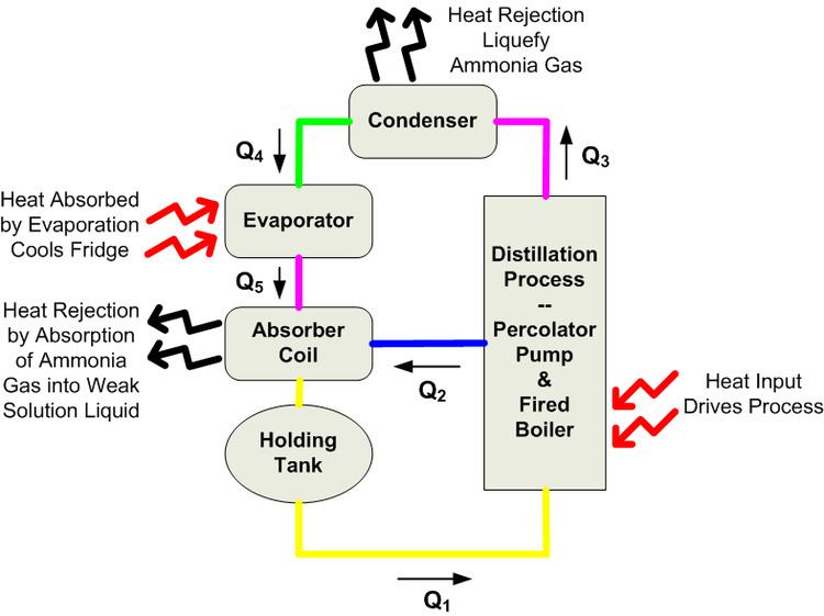
The block diagram shows the flow of fluids (Qx) along with the flow direction arrows. Also, the heat input (endothermic process) and heat rejection (exothermic process) for the respective components has been identified. The fluid flow is as follows:
Q1: The yellow line is the holding tank mixture of liquid water, ammonia, and a rust inhibitor.
Q2: The blue line is the weak solution. The weak solution preferably consists of only water and the rust inhibitor as a result of the distillation process.
Q3: The pink line is pure ammonia gas (anhydrous ammonia). The heat input in the fired boiler causes the liquid ammonia within Q1 to boil (go through a phase change).
Q4: The green line is ammonia liquid. The condenser cools the ammonia gas (Q3) to produce the working fluid which removes the heat from the refrigerated compartment.
Q5: The pink line is once again ammonia gas. The ammonia gas is produced by evaporation of the ammonia liquid (Q4) within the evaporator. The evaporation of the liquid ammonia is due to Dalton's law of partial pressures The pressure vessel which is commonly referenced as a cooling unit in the RV industry has all of the air evacuated and a hydrogen charge of approximately 350psi (~2.4MPa).
Q2 + Q5 → Q1: In the absorber coil the circuit is completed. Q1 is reconstituted due to the fact that ammonia has an affinity for water. The weak solution (Q2) absorbs the ammonia gas thereby returning the ammonia to a liquid state to reenter the boiler and start the process over.
Simplified fluids schematic
The RV fridge simplified fluids schematic more closely resembles the actual cooling unit. (The same color schemes have been use for the fluid flow as the block diagram.)
Boiler
The RV Fridge boiler is the heart of the refrigeration process. It performs two main tasks; one is to separate the ammonia from the water using the process of distillation. The second task that the boiler performs is to pump the fluids which maintains the flow Qx within the cooling unit. The RV Fridge boiler is considered a watertube type boiler which has the advantage of low weight and a high circulation rate which is desirable for mobile applications.
Process flow
Q1 Holding Tank to Percolator Tube
Starting at the holding tank the fluids Q1 are delivered to the boiler through the inner annular tube. Heat is applied and the ammonia changes phase from liquid to gas. The ammonia gas rises up the percolator tube (pump tube) forcing the remaining water that has been depleted of ammonia up the pump tube at the same time.
Q2 Weak Solution
At the top of the percolator tube the water Q2 drops down by the force of gravity into the outer annular tube. This water passes by the heat input to further deplete the flow Q2 of any remaining ammonia. In addition, the flow Q2 also provides preheating (regenerator) for flow Q1 as Q1 moves from the holding tank to the boiler.
Q3 Generation of Refrigerant
From the top of the percolator tube the anhydrous ammonia rises due to its density. The entire boiler assembly and percolator tube are also called a generator because the refrigerant is generated here.
Boiler ammonia accumulator
The ammonia accumulator is a bell shaped chamber. The bottom of the chamber is open to the boiler and the top is closed with the percolator tube passing through. The accumulator fills with ammonia gas from the bottom, this in turn forces out any liquids from within the accumulator. The ammonia accumulator serves two important startup functions as follows:
One is to provide an area where the ammonia bubbles can gather when the heat source is started. This allows large bubbles to rise up the percolator tube upon startup rather than allowing the ammonia in the boiler to rise up the percolator tube without pumping the resulting liquid water.
The second function is to provide an ammonia reserve. When the heat is turned off at the boiler, as the boiler cools the same effect can occur as described above. If the ammonia is depleted from the boiler upon cool down the process cannot restart upon startup. Thus, when the boiler temperature lowers, the ammonia gas trapped in the accumulator will return into solution reconstituting Q1 for a strong ammonia solution in the boiler for an easy startup.
Controls
The controls for the RV Fridge center around controlling the boiler heat source. For the most part the control is binary. If refrigeration is called for, one of the boiler heat sources is turned on. When the refrigerated space is cool enough the boiler heat source is turned off.
RV Fridge controls have not change much in function since 1923 when Kelvinator introduces the first refrigerator control with automatic temperature control. Please see next section Boiler Safety for modern RV Fridge controls.
Pressure
One issue that is faced by any heated pressure vessel is how to prevent catastrophic rupture. This is why the typical RV Fridge has a pressure relief device which is commonly called a PRV. The RV Fridge PRV is very limited because it is a fusible plug. It is reported that the fusible plug will only vent the pressure vessel in the event of a fire. Unfortunately the fusible plug does not prevent a majority of fridge safety issues. The RV fridge fusible plug is a retroactive device which responds to a major failure mode that results in a fire.
Limit thermal stress
One of the first major RV Fridge control changes occurred when the Absorption Refrigeration Protective RV (ARPrv) Controller was invented. The ARPrv control principle of operation is based on the same physics that result in a constant temperature for the boiling of water. The ARP Control simply measures the latent heat of vaporization of ammonia. The ARP detects when Q2 is not flowing by the rise in temperature due to ammonia not being returned to the boiler. When ammonia does not return to the boiler, the sodium chromate is destroyed by excess heat. Once the sodium chromate is destroyed, intergranular corrosion, which leads to stress corrosion cracking, will eventually result in a cooling unit rupture. This discovery has solved most of the operator error issues such as off-level operation of the fridge. The ARPrv controller is a proactive automatic boiler control that limits both thermal stress on the boiler and stress on the working fluids. In addition, by limiting the temperature at the boiler, the pressure in the cooling unit is controlled which in turn increases safety and longevity of the RV Fridge.
Condenser
The RV Fridge condenser cools and liquefies the pure ammonia gas Q3 that rises up from the boiler. The liquefied ammonia Q4 flows from the condenser to the evaporator where the actual refrigeration takes place.
Failure modes
The RV Fridge condenser needs two requirements meet in order for it to sustain the refrigeration cycle. The first is the condenser environment temperature must remain below the condensation temperature of ammonia at the system pressure, otherwise the ammonia will remain in a gaseous state. Therefore, the condenser requires proper air circulation. The second factor for proper operation is that the condenser is level such that the liquid ammonia will flow into the evaporator. When the fridge is operated off-level the ammonia will pool in the condenser. This pooling results in Q4 flow cessation and thus stops the refrigeration process because the ammonia cannot enter the evaporator for cooling of the fridge. In addition, the pooling of ammonia in the condenser prevents the ammonia from returning to the boiler causing complete cessation of the boiler function. When the boiler function stops overheating of the boiler follows.
Evaporator
The RV Fridge evaporator is where cooling of the refrigerated cabinet occurs. Basically all refrigeration process use evaporation for cooling. In the absorption type RV Fridge liquid ammonia Q4 enters from the condenser and flows down the evaporator. Within the evaporator the liquid ammonia comes in contact with the assistant gas which is generally hydrogen. Due to Dalton's law of partial pressures the liquid ammonia Q4 evaporates thereby absorbing heat from within the refrigerated space. Because the ammonia gas Q5 is heavier than the assistant gas, the ammonia gas flows out the bottom of the evaporator.
Construction
The evaporator is located within the foam cabinet in an RV Fridge. When one looks into either the freezer or refrigerated cabinets the back wall will generally have an aluminum plate which may have fins for increasing surface area for the absorption of heat from the refrigerated space. Depending on the type and construction of the RV Fridge, as a rule of thumb, the top half of the evaporator is in thermal contact with the freezer section and the lower half is in contact with the refrigerated section of the cabinet.
Failure modes
Due to the construction of the evaporator there are two failure modes. The first is not a failure of the evaporator but rather the consequence of a failing boiler assembly. As an example, if the fridge has been operated off-level and the boiler is allowed to overheat, the volume of liquid ammonia Q4 is reduced. The reduced ammonia flow Q4 results in the ammonia evaporating before reaching the lower half of the evaporator. As a result, the freezer may be very cold, while the refrigerated space is too warm to prevent food spoilage.
The second mode of failure is due to the evaporator not being sealed properly. Often screws hold the evaporator into place from the inside of the refrigerator. If the screw heads are not sealed, water from inside the cabinet will flow by capillary action into the sealed evaporator space within the foam. Also, the back side of the evaporator has to be sealed so that ambient air cannot infiltrate the sealed evaporator space. When ambient air is allowed to come into contact with the evaporator, condensation results. The result for both of these issues is that water is trapped against the steel evaporator tubing, forming a galvanic cell which will rust a hole in the evaporator, resulting in premature fridge failure.
Absorber
The absorber or absorber coils is where the fluids are recombined to complete the refrigeration fluids circuit. The ammonia gas Q5 drops down from the evaporator into the absorber where it comes into contact with the weak solution Q2 (water) flowing into the top of the absorber coils. When the ammonia vapor Q5 comes into contact with the weak solution liquid Q2, the weak solution absorbs the ammonia gas due to ammonias affinity for water. The absorption of ammonia gas into the water solution is an exothermic process, thus heat needs to be rejected from the absorber coils. The absorber coil is where the heat from within the fridge is rejected into the surroundings.
Failure modes
The absorber itself is not subject to failure due to corrosion or stress when constructed properly. The absorber can be reduced in capacity if the temperatures get too high in the cooling unit compartment. High temperatures slow down the rate at which ammonia gas is reabsorbed (Solubility of Ammonia in Water), therefore this can result in poor cooling within the refrigerated space. A simple test to see if the ammonia is completing the circuit is to feel the absorber coil. If the absorber coil does not heat within an hour of turning on the fridge it is possible that the ammonia is not being produced by the boiler or the ammonia is not completing the circuit. Besides the fridge cabinet temperature, knowing the RV Fridge boiler temperature and the absorber temperature gives one the information to know if the RV Fridge is functioning properly.