
 | ||
Manufacturers Vickers-Armstrongs, Royal Aircraft Establishment | ||
The R.A.E. Vickers Transonic Research Rocket was developed from the Miles M.52 a British supersonic research aircraft a project which was undertaken in top secrecy between 1942 and 1945 to a Ministry of Supply specification E.24/43. The project was cancelled because the Government of the day was persuaded that with the accumulation of data it was felt that the E.24/43 aircraft was unlikely to reach sonic speed. Wind tunnel model tests apparently indicated serious loss of longitudinal stability at high subsonic speed as was then characteristic of existing aircraft. The decision was reached to acquire preliminary experience of flight under transonic conditions using rocket-driven pilotless scale models.The Ministry of Supply (MOS) formed the Guided Projectile Establishment under W. P. Cooke at Westcott, Buckinghamshire, and the Rocket Propulsion Group under A. D. Baxter at RAE, Farnborough. Work commenced in applying German technology, with the Halstead Experimental Centre of the MOS monitoring commercial exploitation.
Contents
Development
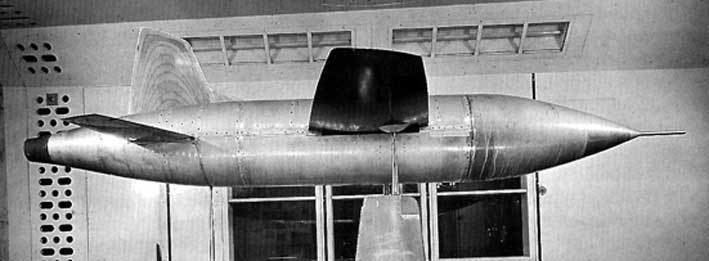
A contract was placed in 1945 with Vickers Armstrong Limited for the design and construction of several test vehicles. Early in 1946 the contract for the E.24/43 was cancelled, since it was felt impossible to ensure safe escape for the pilot in the event of an emergency ejection at high speed. The difficulties surrounding flight at sonic speeds appeared to increase with increasing knowledge. In those circumstances, consideration of an improved version of the E.24/43 was discarded in favour of pilotless models which for the initial tryout were to be 3/10-scale versions of the Miles M.52 design. For drag and stress reasons the operational altitude had to be in the stratosphere, to which altitude the test vehicles would be carried by a parent aircraft, a De havilland Mosquito
Powerplant
The design was to be powered by a 362 kg (800 lbs.) thrust hydrogen peroxide 'hot' motor evolved at Westcott with characteristics drawn from the Walter RI 2031209 ATO unit. This initiated the Beta- and the subsequent Gamma MOS-inspired engines. In October 1948 the Vickers Transonic model flew at 930 mph in level flight at 35,000 ft.
Design
The test vehicle was a 3/10-scale model of the Miles E.24/43 design except for the omission of the distinctive annular air intake of the full-scale aircraft. To maintain the center of gravity (c.g.) it was necessary to include a large balance weight (a!most 1/10 of total all-up weight) in the foremost section of the nose. The layout was further restricted by the need to maintain a constant c.g. position during the consumption of the fuels. This was achieved by placing a small tank ahead of the wing holding one third of the total oxidant (as well as the fuel in the shaped nose tank) and locating the main oxidant tank aft of tile wing. Other large components were placed fore and aft of the wing. In the space below and above the wing centre section were located the air, fuel, oxidant and warm-air pipes, telemetering transmitter, instruments and batteries as well as the autopilot, timing clock, wiring terminal fuses and the connections by which the test vehicle was carried on the parent aircraft. The rear section housed the combustion chamber, radar transponder, smoke-producing fluid, instruments and oscillators for combustion chamber pressure and tailplane angle, servos and dive mechanism for the tailplane which together with the fixed directional fin were fitted to the lower body prior. The single-piece wing was of mahogany with Dural inserts at the leading and trailing edges; it was of biconvex section and of tapered planform with an unswept half-chord line. The Dural inserts formed a convenient dipole-aerial system for the telemetering unit. (A similar arrangement on the tailplane served the radar transponder.)
Operational history
A1: On the last check flight before live firing the parent aircraft descended into a storm at 22,000 ft. When smooth conditions were regained at about 8,000 ft altitude the test vehicle A1 carrying all the prototype examples of instruments and equipment was found to have parted from the aircraft and disappeared beneath the waters of the Bristol Channel.
List of Test Vehicles in Chronological Order
Ref. Type Details
A1 Complete Lost in cloud during early flight trials—30/05/47
A2 Complete First release—rocket motor failed to ignite—08/10/47
A9 Fuselage Rocket motor starting tests. Released from 35,000 ft 29/02/48 fired
A8 Fuselage Rocket motor starting tests• Release from 35,000 if—29/02/48 non firing
A12 Fuselage Rocket motor starting tests. Release from 25,000 ft—ignition fired 05/03/48
All Fuselage Rocket motor starting tests. Release from 25,000 ft—ignition fired 07/06/48
A10 Fuselage Rocket motor starting tests. Release from 35,000 if—explosion in tail 09/06/48
A3 Complete Rocket motor starting tests. Release from 35,000 ft successful 09/10/48
Specifications
General characteristics
Performance