
 | ||
This pulsatile flow generator produces a pulsating water flow by using flexible tubes, a collapsible elastic bladder and a fluid supply. This is a rare phenomenon which still isn't fully understood. What makes this phenomenon unique is the fact that it can generate a pulsatile flow without any use of difficult mechanical engines. There are existing pulsatile flow generators but none of them are as frugal and easy to build as this one. They are also expensive and none of them are based on principle of flow limitation occurring in collapsible tubes.
Contents
Principle
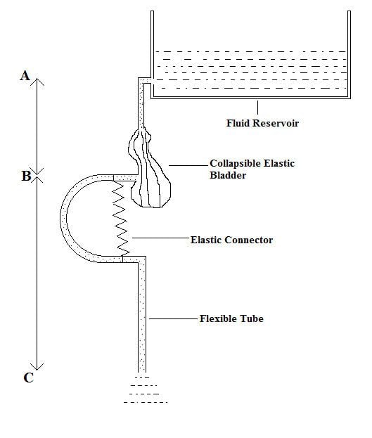
The fluid reservoir is connected to the collabsible bladder. The lower end of the bladder is connected to a flexible tube made of synthetic rubber or PVC. The first bit of the flexible tube that begins at the lower end of the bladder is 'U' shaped by using an elastic connector or a wire spiral. The end of the flexible tube were the water flows out is open to the atmospheric pressure. If the vertical height from the reservoir to the bladder is less than from the ground to the bladder and during a certain flow rate the bladder performs an interesting phenomenon of collapsing and opening along with the generation of a pulsatile flow of the liquid. The cause of this phenomenon can be explained by the functioning of the Starling resistor which produces self-excited oscillations caused by fluid-structure interaction in an elastic tube due to sudden stoppage of flow. This pulsatile flow generator can actually be seen as a modification of the Starling resistor.
As liquid starts filling the collabsible bladder a pressure drop inside the bladder causes the bladder to collapse and cutting off the fluid flow into the 'U' shaped tube (sudden stoppage of flow). As a result, a pulsatile flow is produced because of the continuously collapsing bladder. As the collapsing goes on the ‘U’ shaped tube strikes down with strong force pulling the spring down which was supporting the ‘U’ shaped tube from above. The force generated can be recorded directly with a dynamometer connected to the upper limb of the 'U' shaped tube.
flow rate
The flow rate can be adjusted to change the frequency of the collapsing bladder (collapse per minute). As the flow rate increases, the frequency decreases. Consequently, the flow rate is inversely proportional to the frequency.
The velocity of the fluid at which it enters the bladder is lower than the velocity at which the fluid leaves the construction at the end of the flexible tube. Still, the flow rate remains the same.
height
When changing the height of the bladder from the ground the frequency of the collapsing bladder changes as well. As the height increases, the frequency of collapses per minute decreases.
spring constant
Using Hooke's law the spring constant of the elastic connector can be calculated.
If the spring constant is changed the frequency remains nearly the same as with other spring constants.
Methods of measurement
Since there is little known about this phenomenon it is important to conduct a research and to obtain as much information as possible about it. Various methods of measurement can be used to measure the oscillations.
Dynamometer
As already mentioned the force generated can be recorded directly with a dynamometer connected to the upper limb of the 'U'-shaped tube.
Planar Hall sensor
In this experiment a magnet is connected to the lower flexible tube. As the bladder begins to oscillate the lower part begins to move vertically up and down. Subsequently the Hall sensor measures the change in anisotropic magnetoresistance and gives a graph which shows the vertical variation in militesla.
Differential voltage sensor
The magnet from the experiment with the planar Hall sensor stays connected to the flexible tube. Instead of measuring the change in magnetoresistance the magnet moves vertically through an electromagnetic coil which creates electromagnetic induction which can be measured by using a differential voltage sensor.
Motion sensor
By using a motion sensor, the vertical movement of the flexible tube can be measured by observing the difference in distance of a particular point on the flexible tube. As the tube moves up and down the motion sensor will observe a repeating difference in distance.