
 | ||
An aircraft propeller (noun /prəˈpel·ər/) or airscrew converts rotary motion from an engine or other mechanical power source, to provide propulsive force. It comprises a rotating power-driven hub, to which are attached several radial airfoil-section blades such that the whole assembly rotates about a longitudinal axis. The blade pitch may be fixed, manually variable to a few set positions, or of the automatically-variable "constant-speed" type.
Contents
- History
- Theory and design of aircraft propellers
- Forces acting on a propeller
- Curved propeller blades
- Varying pitch
- Variable pitch
- Constant speed
- Feathering
- Reverse pitch
- Counter rotating propellers
- Contra rotating propeller
- Aircraft fans
- References
The propeller attaches to the power source's driveshaft either directly or, especially on larger designs, through reduction gearing.
Most early aircraft propellers were carved by hand from solid or laminated wood, while metal construction later became popular. More recently, composite materials are becoming increasingly used.
Propellers are only suitable for use at subsonic airspeeds up to around 480 mph (770 km/h), as above this speed the blade tip speed begins to go supersonic, with the consequent shockwaves causing high drag and other mechanical difficulties.
History
The earliest references for vertical flight came from China. Since around 400 BC, Chinese children have played with bamboo flying toys. This bamboo-copter is spun by rolling a stick attached to a rotor between ones hands. The spinning creates lift, and the toy flies when released. The 4th-century AD Daoist book Baopuzi by Ge Hong (抱朴子 "Master who Embraces Simplicity") reportedly describes some of the ideas inherent to rotary wing aircraft.
Designs similar to the Chinese helicopter toy appeared in Renaissance paintings and other works.
It was not until the early 1480s, when Leonardo da Vinci created a design for a machine that could be described as an "aerial screw", that any recorded advancement was made towards vertical flight. His notes suggested that he built small flying models, but there were no indications for any provision to stop the rotor from making the craft rotate. As scientific knowledge increased and became more accepted, men continued to pursue the idea of vertical flight. Many of these later models and machines would more closely resemble the ancient bamboo flying top with spinning wings, rather than Leonardo's screw.
In July 1754, Russian Mikhail Lomonosov had developed a small coaxial modeled after the Chinese top but powered by a wound-up spring device and demonstrated it to the Russian Academy of Sciences. It was powered by a spring, and was suggested as a method to lift meteorological instruments. In 1783, Christian de Launoy, and his mechanic, Bienvenu, used a coaxial version of the Chinese top in a model consisting of contrarotating turkey flight feathers as rotor blades, and in 1784, demonstrated it to the French Academy of Sciences. A dirigible airship was described by Jean Baptiste Marie Meusnier presented in 1783. The drawings depict a 260-foot-long (79 m) streamlined envelope with internal ballonnets that could be used for regulating lift. The airship was designed to be driven by three propellers. In 1784 Jean-Pierre Blanchard fitted a hand-powered propeller to a balloon, the first recorded means of propulsion carried aloft. Sir George Cayley, influenced by a childhood fascination with the Chinese flying top, developed a model of feathers, similar to that of Launoy and Bienvenu, but powered by rubber bands. By the end of the century, he had progressed to using sheets of tin for rotor blades and springs for power. His writings on his experiments and models would become influential on future aviation pioneers.
William Bland sent designs for his "Atmotic Airship" to the Great Exhibition held in London in 1851, where a model was displayed. This was an elongated balloon with a steam engine driving twin propellers suspended underneath. Alphonse Pénaud developed coaxial rotor model helicopter toys in 1870, also powered by rubber bands. In 1872 Dupuy de Lome launched a large navigable balloon, which was driven by a large propeller turned by eight men. Hiram Maxim built a craft that weighed 3.5 tons, with a 110-foot (34-meter) wingspan that was powered by two 360-horsepower (270-kW) steam engines driving two propellers. In 1894, his machine was tested with overhead rails to prevent it from rising. The test showed that it had enough lift to take off. One of Pénaud's toys, given as a gift by their father, inspired the Wright brothers to pursue the dream of flight. The twisted airfoil (aerofoil) shape of an aircraft propeller was pioneered by the Wright Brothers. While some earlier engineers had attempted to model air propellers on marine propellers, the Wright Brothers realized that a propeller is essentially the same as a wing, and were able to use data from their earlier wind tunnel experiments on wings, introducing a twist along the length of the blades. This was necessary to maintain a more uniform angle of attack of the blade along its length. Their original propeller blades had an efficiency of about 82%, compared to the 90% of modern propellers.
Mahogany was the wood preferred for propellers through World War I, but wartime shortages encouraged use of walnut, oak, cherry and ash. Alberto Santos Dumont was another early pioneer, having designed propellers before the Wright Brothers (albeit not as efficient) for his airships. He applied the knowledge he gained from experiences with airships to make a propeller with a steel shaft and aluminium blades for his 14 bis biplane in 1906. Some of his designs used a bent aluminium sheet for blades, thus creating an airfoil shape. They were heavily undercambered, and this plus the absence of lengthwise twist made them less efficient than the Wright propellers. Even so, this was perhaps the first use of aluminium in the construction of an airscrew. Originally, a rotating airfoil behind the aircraft, which pushes it, was called a propeller, while one which pulled from the front was a tractor. Later the term 'pusher' became adopted for the rear-mounted device in contrast to the tractor configuration and both became referred to as 'propellers' or 'airscrews'. The understanding of low speed propeller aerodynamics was fairly complete by the 1920s, but later requirements to handle more power in a smaller diameter have made the problem more complex.
Theory and design of aircraft propellers
A well-designed propeller typically has an efficiency of around 80% when operating in the best regime. The efficiency of the propeller is influenced by the angle of attack (α). This is defined as α = Φ - θ, where θ is the helix angle (the angle between the resultant relative velocity and the blade rotation direction) and Φ is the blade pitch angle. Very small pitch and helix angles give a good performance against resistance but provide little thrust, while larger angles have the opposite effect. The best helix angle is when the blade is acting as a wing producing much more lift than drag. Angle of attack is similar to advance ratio, for propellers.
A propeller's efficiency is determined by
Propellers are similar in aerofoil section to a low-drag wing and as such are poor in operation when at other than their optimum angle of attack. Therefore, some propellers use a variable pitch mechanism to alter the blades' pitch angle as engine speed and aircraft velocity are changed.
A further consideration is the number and the shape of the blades used. Increasing the aspect ratio of the blades reduces drag but the amount of thrust produced depends on blade area, so using high-aspect blades can result in an excessive propeller diameter. A further balance is that using a smaller number of blades reduces interference effects between the blades, but to have sufficient blade area to transmit the available power within a set diameter means a compromise is needed. Increasing the number of blades also decreases the amount of work each blade is required to perform, limiting the local Mach number - a significant performance limit on propellers.
A propeller's performance suffers as the blade speed nears the transonic. As the relative air speed at any section of a propeller is a vector sum of the aircraft speed and the tangential speed due to rotation, a propeller blade tip will reach transonic speed well before the aircraft does. When the airflow over the tip of the blade reaches its critical speed, drag and torque resistance increase rapidly and shock waves form creating a sharp increase in noise. Aircraft with conventional propellers, therefore, do not usually fly faster than Mach 0.6. There have been propeller aircraft which attained up to the Mach 0.8 range, but the low propeller efficiency at this speed makes such applications rare.
There have been efforts to develop propellers for aircraft at high subsonic speeds. The 'fix' is similar to that of transonic wing design. The maximum relative velocity is kept as low as possible by careful control of pitch to allow the blades to have large helix angles; thin blade sections are used and the blades are swept back in a scimitar shape (Scimitar propeller); a large number of blades are used to reduce work per blade and so circulation strength; contra-rotation is used. The propellers designed are more efficient than turbo-fans and their cruising speed (Mach 0.7–0.85) is suitable for airliners, but the noise generated is tremendous (see the Antonov An-70 and Tupolev Tu-95 for examples of such a design).
Forces acting on a propeller
Five forces act on the blades of an aircraft propeller in motion. Some of these forces can be arranged to counteract each other, reducing the overall mechanical stresses imposed.
Curved propeller blades
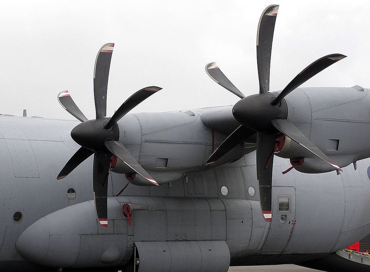
Since the 1940s, propellers and propfans with swept tips or curved "scimitar-shaped" blades have been studied for use in high-speed applications so as to delay the onset of shockwaves, in similar manner to wing sweepback, where the blade tips approach the speed of sound. The Airbus A400M turboprop transport aircraft is expected to provide the first production example: note that it is not a propfan because the propellers are not mounted directly to the engine shaft but are driven through reduction gearing.
Varying pitch
The purpose of varying pitch angle is to maintain an optimal angle of attack for the propeller blades, giving maximum efficiency throughout the flight regime.
Variable pitch
Early pitch control settings were pilot operated, either with a small number of preset positions or continuously variable.
Following World War I, automatic propellers were developed to maintain an optimum angle of attack. This was done by balancing the centripetal twisting moment on the blades and a set of counterweights against a spring and the aerodynamic forces on the blade. Automatic props had the advantage of being simple, lightweight, and requiring no external control, but a particular propeller's performance was difficult to match with that of the aircraft's power plant.
Modern light aircraft and advanced homebuilt aircraft sometimes have variable pitch (VP) propellers. These tend to be electrically operated and controlled manually or by computer. The V-Prop is self-powering and self-governing.
A simpler version was the spring-loaded "two-speed" VP prop, which was set to fine for takeoff, and then triggered to coarse once in cruise, the propeller then staying in coarse for the remainder of the flight. An even simpler version is the ground-adjustable propeller, which may be adjusted on the ground, but is effectively a fixed-pitch prop once airborne.
Constant speed
An improvement on the automatic type was the constant-speed propeller. This type automatically adjusts the blade pitch according to the engine speed, thereby maintaining a constant engine speed for any given manual control setting. Constant-speed propellers allow the pilot to set a rotational speed according to the need for maximum engine power or maximum efficiency, and a propeller governor acts as a closed-loop controller to vary propeller pitch angle as required to maintain the selected engine speed. In most aircraft this system is hydraulic, with engine oil serving as the hydraulic fluid. However, electrically controlled propellers were developed during World War II and saw extensive use on military aircraft, and have recently seen a revival in use on homebuilt aircraft.
Feathering
On some variable-pitch propellers, the blades can be rotated parallel to the airflow to reduce drag in case of an engine failure. This is called feathering, a term borrowed from rowing. On single-engined aircraft, whether a powered glider or turbine-powered aircraft, the effect is to increase the gliding distance. On a multi-engine aircraft, feathering the propeller on a failed engine helps the aircraft maintain altitude with the reduced power from the remaining engines.
Most feathering systems for reciprocating engines sense a drop in oil pressure and move the blades toward the feather position, and require the pilot to pull the propeller control back to disengage the high-pitch stop pins before the engine reaches idle RPM. Turboprop control systems usually utilize a negative torque sensor in the reduction gearbox which moves the blades toward feather when the engine is no longer providing power to the propeller. Depending on design, the pilot may have to push a button to override the high-pitch stops and complete the feathering process, or the feathering process may be totally automatic.
Reverse pitch
In some aircraft, such as the C-130 Hercules, the pilot can manually override the constant-speed mechanism to reverse the blade pitch angle, and thus the thrust of the engine (although the rotation of the engine itself does not reverse). This is used to help slow the plane down after landing in order to save wear on the brakes and tires, but in some cases also allows the aircraft to back up on its own - this is particularly useful for getting floatplanes out of confined docks. See also Thrust reversal.
Counter-rotating propellers
Counter-rotating propellers are sometimes used on twin-, and other multi-engine, propeller-driven aircraft. The propellers of these wing-mounted engines turn in opposite directions from those on the other wing. Generally, the propellers on both engines of most conventional twin-engined aircraft spin clockwise (as viewed from the rear of the aircraft). Counter-rotating propellers generally spin clockwise on the left engine, and counter-clockwise on the right. The advantage of counter-rotating propellers is to balance out the torque effects of high-power piston engine as well as gyroscopic precession effects (p-factor) during flight manoeuvres, eliminating the problem of the critical engine. These are sometimes referred to as "handed" propellers since there are left hand and right hand versions of each prop.
Contra-rotating propeller
A contra-rotating propeller or contra-prop places two counter-rotating propellers on concentric drive shafts so that one sits immediately 'downstream' of the other propeller. This provides the benefits of counter-rotating propellers for a single powerplant. The forward propeller provides the majority of the thrust, while the rear propeller also recovers energy lost in the swirling motion of the air in the propeller slipstream. Contra-rotation also increases the ability of a propeller to absorb power from a given engine, without increasing propeller diameter. However the added cost, complexity, weight and noise of the system rarely make it worthwhile and it is only used on high-performance types where ultimate performance is more important than efficiency.
Aircraft fans
A fan is a propeller with a large number of blades. A fan therefore produces a lot of thrust for a given diameter but the closeness of the blades means that each strongly affects the flow around the others. If the flow is supersonic, this interference can be beneficial if the flow can be compressed through a series of shock waves rather than one. By placing the fan within a shaped duct, specific flow patterns can be created depending on flight speed and engine performance. As air enters the duct, its speed is reduced while its pressure and temperature increase. If the aircraft is at a high subsonic speed this creates two advantages: the air enters the fan at a lower Mach speed; and the higher temperature increases the local speed of sound. While there is a loss in efficiency as the fan is drawing on a smaller area of the free stream and so using less air, this is balanced by the ducted fan retaining efficiency at higher speeds where conventional propeller efficiency would be poor. A ducted fan or propeller also has certain benefits at lower speeds but the duct needs to be shaped in a different manner than one for higher speed flight. More air is taken in and the fan therefore operates at an efficiency equivalent to a larger un-ducted propeller. Noise is also reduced by the ducting and should a blade become detached the duct would help contain the damage. However the duct adds weight, cost, complexity and (to a certain degree) drag.