
 | ||
A prism coupler is a prism designed to couple a substantial fraction of the power contained in a beam of light (e.g., a laser beam) into a thin film to be used as a waveguide without the need for precision polishing of the edge of the film, without the need for sub-micrometer alignment precision of the beam and the edge of the film, and without the need for matching the numerical aperture of the beam to the film. Using a prism coupler, a beam coupled into a thin film can have a diameter hundreds of times the thickness of the film. Invention of the coupler contributed to the initiation of a field of study known as integrated optics.
Contents
History
The theory underlying the prism coupler was first published in the Soviet Union. This work was not known in the US. Starting in 1969, Shubert, Harris, and Polky at the University of Washington, and, independently, Tien, Ulrich, and Martin, at Bell Laboratories described the first experiments with prism coupling and its underlying theory. This was done with a view toward device applications of thin films.
Configuration
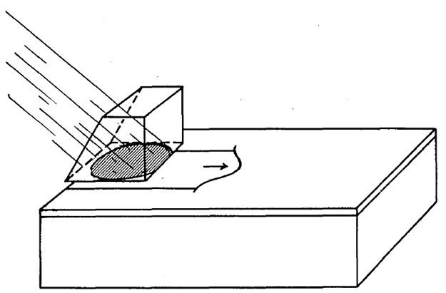
A prism coupler is used to couple the power from an incident laser beam into a thin film. The film lies on a substrate such as a glass microscope slide and might have a thickness of the order of the wavelength of the incident light (0.550 μm for green light). The refractive index of the film is made greater than that of the glass slide, the film can serve as a dielectric planar waveguide for light via total internal reflection off the film–glass interface (and film–air interface). The prism coupler consists of a near cube of high–refractive-index glass and a second thin film at the bottom that contacts the waveguide film and serves the function of partially containing the guided wave over the coupling distance. The thin film at the bottom of the prism is referred to as the tunneling layer. The tunneling layer must have a lower refractive index than the waveguide film and may actually be implemented as a layer of air. The thickness of the tunneling layer will be on the order of a fraction of a wavelength (tens to hundreds of nanometers for visible light).
The prism and tunneling layer are pressed against the waveguide film. The beam enters the front face of the prism and strikes the tunneling layer somewhat more than half a beam width away from the face opposite the entry face of the prism. The ranking of refractive indices of the four regions of the combined coupler and waveguide structure must be as follows: the refractive index of the glass slide and the tunneling layer must be lowest, next is the refractive index of the guide film, and highest is the index of the prism.
Theory
A prism coupler may be explained in terms of the reciprocity theorem. The reciprocity theorem permits the relative power coupled into the thin film by an incident beam to be computed from the solution to a reciprocal problem. In the reciprocal problem, a waveguide mode in the film (travelling to the left in the first figure) is incident on the prism coupler. Barring significant scattering at the prism interface, the waveguide mode in the reciprocal problem retains its form as a mode and propagates under the prism, losing power as it propagates due to radiation into the prism. The power in the prism emerges as a collimated beam at an angle determined by the propagation constant of the waveguide mode and the refractive index of the prism. Radiation into the prism occurs because the evanescent tail of the waveguide mode touches the bottom of the prism. The waveguide mode tunnels through the tunneling layer.
Efficient coupling of light into the film occurs when the incident beam (arriving from the left shown in the first figure), evaluated at the bottom face of the prism, has the same shape as the radiated beam in the reciprocal problem. When the power in both the incident beam and the reciprocal waveguide mode is normalized, the fractional coupling amplitude is expressed as an integral over the product of the incident wave and the radiated reciprocal field. The integral is a surface integral taken over the bottom face of the prism. From such an integral we deduce three key features:
- To couple in a significant fraction of the incident power, the incident beam must arrive at the angle that renders it phase matched to the waveguide mode.
- The transverse behavior of the waveguide mode launched in the film (transverse to the direction of propagation) will be essentially that of the incident beam.
- If the thickness of the tunneling layer is adjusted appropriately, it is possible, in principle, to couple nearly all the light in the beam into the waveguide film.
Suppressing the transverse part of the representation for the fields, and taking x as direction to the left in Fig. 1, the waveguide mode in the reciprocal problem takes the monotonically decreasing form
where α(x) is the attenuation rate and
The associated transverse field at the bottom of the prism takes the form
with A a normalization constant.
The transverse field of the incident beam will have the form
where f(x) is a normalized Gaussian, or other beam form, and βin is the longitudinal component of the propagation constant of the incident beam.
When βin = βw, integration of
yields the coupling amplitude. Adjusting α(x) permits the coupling to approach unity, barring significant geometry-dependent diffractive effects.
Remarks
The Goos-Hänchen shift describes the displacement of the center point of an optical beam when it undergoes total reflection from the interface between two semi-infinite regions of different refractive index. The displacement is generally of the order of the wavelength of light. If the reflection of a beam from a sandwich structure that consists of a semi-infinite prism, a tunneling layer, a waveguide film layer, and a semi-infinite glass slide is investigated, the shift will be found to be much larger as a consequence of the excitation of the guided wave. Terminating the upper (prism) region just beyond the midpoint of the incident beam traps the light of the beam in the waveguide mode in the film.
Excitation of the guided wave by an incident beam can also be viewed as a problem in coupled modes, the modes being the waveguide mode and a representation for the incident beam. Power introduced into one branch of a coupled mode structure can transfer to the other branch along the structure.
Measurement applications
Prism couplers are instruments used to measure the refractive index/birefringence and thickness of dielectric and polymer films. Since refractive indices of a material depend upon the wavelength of the electromagnetic radiation transmitted, a monochromatic laser is used in conjunction with a prism of known refractive index. The laser beam is directed through a side of the prism, bent, and is normally reflected back out the opposite side into a photo detector. However, at certain values of the incident angle theta, the beam does not reflect back out, but instead is transmitted through the base into the film sample. These angles are called "mode angles". A computer-driven rotary table varies the incident angle of the laser. The first mode angle found determines the refractive index, and the angle difference from one mode to the next determines the sample thickness.
Prism couplers also allow for coupling light in and out of a waveguide without exposing the cross-section of the waveguide (edge coupling). To achieve this a phase matching condition is required between the propagation constant of the mth mode in the waveguide
where
where