
 | ||
Pressure Volume loops are widely used in basic and preclinical research. Left ventricular PV loops are considered to be the gold standard for hemodynamic assessment and are widely used in research to evaluate cardiac performance. While it has long been possible to measure pressure in real time from the left ventricle, measuring the volume was technically more difficult.
Contents
- Sonomicrometer method
- Conductance catheter technique
- Theory
- Calibration and correction
- Parameters
- References
The use of ultrasonic sonomicrometry and the development of the conductance catheter triggered renewed interest in PV loops studies. In sonomicrometry, small ultrasonic transducers (usually referred to as "crystals") transmit signals to each other, and the distance between them is accurately determined based on the transit-time of the signals. By knowing the long and short axis lengths of the ventricle, ventricular volume is easily and accurately determined. Conductance cathethers measure instantaneous conductance in the left ventricle, which is then converted to blood volume using complex formulas and usually after determining and applying various correction factors. Typically only one method is used to perform PV studies in research settings.
The miniaturization of sonomicrometer crystals and pressure catheters have made mice PV loop studies feasible and more common.
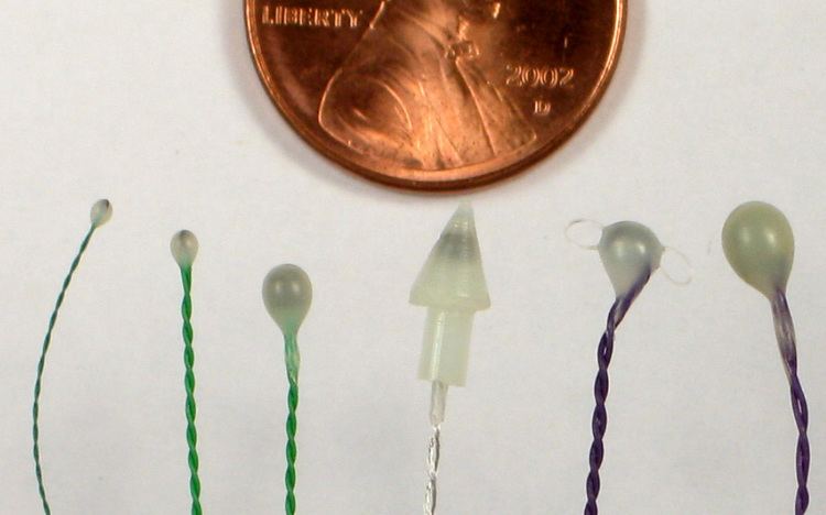
Sonomicrometer method
A sonomicrometer system is composed of an electronic signal-processing unit that is connected to small ultrasonic transducers (crystals). A computer acting as a data acquisition and display device obtains data in real time from the signal processor unit, while the crystals are implanted in or on the left ventrical. As few as 2 or as many as 6 crystals can be used to perform 1-axis, 2-axis, or 3-axis length measurements of the axial planes of the heart, usually at a rate of 200 to 2000 times per second. A typical sonomicrometer system has a resolution of 12 micrometres, enabling high-resolution measurements of the axial lengths.
Ventricular volume is computed directly (either in micro-liters or milli-liters) by combining the axial length measurements in standard spherical or ellipsoidal volume equations:
When the axial measurements are acquired in terms of millimeters, then the volume units in these equations will be in terms of milliliters.
Conductance catheter technique
A conductance catheter contains two or more ring-shaped electrodes along its length. When a high-frequency low-amplitude constant current is passed through the outer electrodes to generate an electric field, the potential difference between any pair of inner electrodes is inversely proportional to the amount of conductive material at that site.
Conductance is defined as the applied current divided by the voltage measured between two adjacent electrodes.
The conductance catheter technique has no major drawbacks but requires careful calibration of conductance signals. Other techniques exist but this article focuses on the well-established conductance catheter technique.
(NOTE: For typical catheter configurations the linear relationship of the inverse potential difference to the amount of material is only an approximation. It is only valid for volumes where the diameter of that volume is less than the distance between the measuring electrodes.)
Theory
The formula by Baan et al. (1984) for obtaining ventricular volume is as follows:
where
The conductance measured by the catheter is actually the conductance of the blood and of the surrounding myocardial tissue. This latter conductance is called the parallel conductance (GP).
Calibration and correction
From the above equation, it can be seen that the volume measurement requires the knowledge of α, ρ, L, and GP.
The equation may be considered to be a straight line of the form y = mx + b, where m (the gain) is a combination of the three terms 1/α, ρ, and L2 and b (the offset) is GP.
L is available from catheter data sheets, while ρ can be measured directly using appropriate equipment.
Ideally, gain should be determined in every experiment. While L is known and ρ can be measured, the α factor poses more difficulties. Indeed, the only way to obtain a reliable gain (encompassing α) involves directly measuring cardiac output. Therefore, for most purposes, an educated estimate is used based on values found in the literature.
To take into account the parallel conductance, GP, the most common method involves injection of hypertonic saline into the subject—enough to temporarily reduce blood resistance, and therefore increase preload, but not so much as to alter haemodynamics. The minimum and maximum volumes (Vmax and Vmin) from each loop in the series of loops are plotted on a graph. Vmax and Vmin lines are extrapolated and at their point of intersection, where Vmax is equal to Vmin, must be zero—conductance is parallel conductance only. The volume at this point is the correction volume.
Admittance techniques offer an alternative to the saline bolus as a means of determining GP.
Parameters
Several parameters can be calculated for each loop (e.g. end-diastolic pressure, end-systolic pressure, ejection and filling intervals, contractility index, stroke volume, and ejection fraction).
More importantly, other interesting parameters are derived from series of loops obtained under changing conditions. For example, the end-diastolic pressure-volume relationship (EDPVR) and end-systolic pressure-volume relationship (ESPVR) are derived from series of loops obtained by slowly inflating a balloon to occlude the inferior vena cava, a procedure that reduces cardiac preload.
EDPVR and ESPVR are valuable because they are load-independent indices of left ventricular function. They also measure left ventricle Compliance/Stiffness (EDPVR) and Contractility (ESPVR) respectively.
Other parameters derived from series of loops are: