
 | ||
Pre-charge of the powerline voltages in a high voltage DC application is a preliminary mode which current-limits the power source such that a controlled rise time of the system voltage during power up is achieved.
Contents
- Background inrush currents into capacitors
- Definition of a pre charge function
- Benefits of pre charging
- Applications in high voltage power systems
- References
When a high-voltage system is designed appropriately to handle the flow of maximum rated power through its distribution system, the components within the system can still undergo considerable stress upon the system "power up". In some applications, the occasion to activate the system is a rare occurrence, such as in commercial utility power distribution which is typically on almost all of the time. Yet in other systems such as in vehicle applications, activation will occur with every individual use of the system. When a long life of the components and a high reliability of the high voltage system is needed, then a power-up method which reduces and limits the power-up stress is required.
Background: inrush currents into capacitors
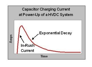
Inrush currents into capacitive components are a key concern in power-up stress to components. When DC input power is applied to a capacitive load, the step response of the voltage input will cause the input capacitor to charge. The capacitor charging starts with an inrush current and ends with an exponential decay down to the steady state condition. When the magnitude of the inrush peak is very large compared to the maximum rating of the components, then component stress is to be expected. The current into a capacitor is known to be
The objective of a pre-charge function is to limit the magnitude of the inrush current into capacitive loads during power-up. This may take several seconds depending on the system. In general, higher voltage systems benefit from longer pre-charge times during power-up.
Consider an example where a high voltage source powers up a typical electronics control unit which has an internal power supply with 11000 µF input capacitance. When powered from a 28 V source, the inrush current into the electronics unit would approach 31 amperes in 10 milliseconds. If that same circuit is activated by a 610 V source, then the inrush current would approach 670 A in 10 milliseconds. It is wise not to allow unlimited inrush currents from high voltage power distribution system activation into capacitive loads: instead the inrush current should be controlled to avoid power-up stress to components.
Definition of a pre-charge function
The functional requirement of the high voltage pre-charge circuit is to minimize the peak current out from the power source by slowing down the dV/dT of the input power voltage such that a new “pre-charge mode” is created. Of course the inductive loads on the distribution system must be switched off during the precharge mode. While pre-charging, the system voltage will rise slowly and controllably with power-up current never exceeding the maximum allowed. As the circuit voltage approaches near steady state, then the pre-charge function is complete. Normal operation of a pre-charge circuit is to terminate pre-charge mode when the circuit voltage is 90% or 95% of the operating voltage. Upon completion of pre-charging, the pre-charge resistance is switched out of the power supply circuit and returns to a low impedance power source for normal mode. The high voltage loads are then powered up sequentially.
The simplest inrush-current limiting system, used in many consumer electronics devices, is a NTC resistor. When cold, its high resistance allows a small current to pre-charge the reservoir capacitor. After it warms up, its low resistance more efficiently passes the working current.
Many active power factor correction systems also include soft start.
If the example circuit from before is used with a pre-charge circuit which limits the dV/dT to less than 600 volts per second, then the inrush current will be reduced from 670 amperes to 7 amperes. This is a “kinder and gentler” way to activate a high voltage DC power distribution system.
Benefits of pre-charging
The primary benefit of avoiding component stress during power-up is to realize a long system operating life due to reliable and long lasting components.
There are additional benefits: pre-charging reduces the electrical hazards which may occur when the system integrity is compromised due to hardware damage or failure. Activating the high voltage DC system into a short circuit or a ground fault or into unsuspecting personnel and their equipment can have undesired effects. Arc flash will be minimized if a pre-charge function slows down the activation time of a high voltage power-up. A slow pre-charge will also reduce the voltage into a faulty circuit which builds up while the system diagnostics come on-line. This allows a diagnostic shut down before the fault is fully realized in worst case proportions.
In cases where unlimited inrush current is large enough to trip the source circuit breaker, a slow precharge may even be required to avoid the nuisance trip.
Pre-charging is commonly used in battery electric vehicle applications. The current to the motor is regulated by a controller that employs large capacitors in its input circuit. Such systems typically have contactors (a high-current relay) to disable the system during inactive periods and to act as an emergency disconnect should the motor current regulator fail in an active state. Without pre-charge the high voltage across the contactors and inrush current can cause a brief arc which will cause pitting of the contacts. Pre-charging the controller input capacitors (typically to 90 to 95 percent of applied battery voltage) eliminates the pitting problem. The current to maintain the charge is so low that some systems apply the pre-charge at all times other than when charging batteries, while more complex systems apply pre-charge as part of the starting sequence and will defer main contactor closure until the pre-charge voltage level is detected as sufficiently high.