
 | ||
The Pound–Drever–Hall (PDH) technique is a widely used and powerful approach for stabilizing the frequency of light emitted by a laser by means of locking to a stable cavity. The PDH technique has a broad range of applications including interferometric gravitational wave detectors, atomic physics, and time measurement standards, many of which also use related techniques such as frequency modulation spectroscopy. Named after R. V. Pound, Ronald Drever, and John L. Hall, the PDH technique was described in 1983 by Drever, Hall and others working at the University of Glasgow and the U. S. National Bureau of Standards. This optical technique has many similarities to an older frequency-modulation technique developed by Pound for microwave cavities.
Contents
Since a wide range of conditions contribute to determine the linewidth produced by a laser, the PDH technique provides a means to control and decrease the laser's linewidth, provided an optical cavity that is more stable than the laser source. Alternatively, if a stable laser is available, the PDH technique can be used to stabilize and/or measure the instabilities in an optical cavity length. The PDH technique responds to the frequency of laser emission independently of intensity, which is significant because many other methods that control laser frequency, such as a side-of-fringe lock are also affected by intensity instabilities.
Laser stabilization
In recent years the Pound–Drever–Hall technique has become a mainstay of laser frequency stabilization. Frequency stabilization is needed for high precision because all lasers demonstrate frequency wander at some level. This instability is primarily due to temperature variations, mechanical imperfections, and laser gain dynamics, which change laser cavity lengths, laser driver current and voltage fluctuations, atomic transition widths, and many other factors. PDH locking offers one possible solution to this problem by actively tuning the laser to match the resonance condition of a stable reference cavity.
The ultimate linewidth obtained from PDH stabilization depends on a number of factors. From a signal analysis perspective, the noise on the locking signal can not be any higher than that posed by the shot noise limit. However, this constraint dictates how closely the laser can be made to follow the cavity. For tight locking conditions, the linewidth depends on the absolute stability of the cavity, which can reach the limits imposed by thermal noise. Using the PDH technique, optical linewidths below 40 mHz have been demonstrated.
Applications
Prominently, the field of interferometric gravitational wave detection depends critically on enhanced sensitivity afforded by optical cavities. The PDH technique is also used when narrow spectroscopic probes of individual quantum states are required, such as atomic physics, time measurement standards, and quantum computers.
Overview of technique
Phase modulated light, consisting of a carrier frequency and two side bands, is directed onto a two-mirror cavity. Light reflected off the cavity is measured using a high speed photodetector, the reflected signal consists of the two unaltered side bands along with a phase shifted carrier component. The photodetector signal is mixed down with a local oscillator, which is in phase with the light modulation. After phase shifting and filtering, the resulting electronic signal gives a measure of how far the laser carrier is off resonance with the cavity and may be used as feedback for active stabilization. The feedback is typically carried out using a PID Controller which takes the PDH error signal readout and converts it into a voltage that can be fed back to the laser to keep it locked on resonance with the cavity.
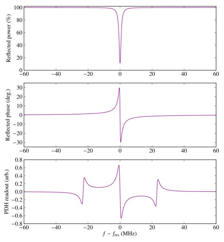
PDH readout function
The PDH readout function gives a measure of the resonance condition of a cavity. By taking the derivative of the cavity transfer function (which is symmetric and even) with respect to frequency, it is an odd function of frequency and hence indicates not only whether there is a mismatch between the output frequency ω of the laser and the resonant frequency ωres of the cavity, but also whether ω is greater or less than ωres. The zero-crossing of the readout function is sensitive only to intensity fluctuations due to the frequency of light in the cavity and insensitive to intensity fluctuations from the laser itself.
Light of frequency f = ω/2π can be represented mathematically by its electric field, E0eiωt. If this light is then phase-modulated by βsin(ωmt), the resulting field Ei is
This field may be regarded as the superposition of three components. The first component is an electric field of angular frequency ω, known as the carrier, and the second and third components are fields of angular frequency ω + ωm and ω − ωm, respectively, called the sidebands.
In general, the light Er reflected out of a Fabry–Pérot two-mirror cavity is related to the light Ei incident on the cavity by the following transfer function:
where α = ωL/c, and where r1 and r2 are the reflection coefficients of mirrors 1 and 2 of the cavity, and t1 and t2 are the transmission coefficients of the mirrors.
Applying this transfer function to the phase-modulated light Ei gives the reflected light Er:
The power Pr of the reflected light is proportional to the square magnitude of the electric field, Er* Er, which after some algebraic manipulation can be shown to be
Here P0 ∝ |E0|2 is the power of the light incident on the Fabry–Pérot cavity, and χ is defined by
This χ is the ultimate quantity of interest; it is an antisymmetric function of ω − ωres. It can be extracted from Pr by demodulation. First, the reflected beam is directed onto a photodiode, which produces a voltage Vr that is proportional to Pr. Next, this voltage is mixed with a phase-delayed version of the original modulation voltage to produce V′r:
Finally, V′r is sent through a low-pass filter to remove any sinusoidally oscillating terms. This combination of mixing and low-pass filtering produces a voltage V that contains only the terms involving χ:
In theory, χ can be completely extracted by setting up two demodulation paths, one with φ = 0 and another with φ = π/2. In practice, by judicious choice of ωm it is possible to make χ almost entirely real or almost entirely imaginary, so that only one demodulation path is necessary. V(ω), with appropriately chosen φ, is the PDH readout signal.