
 | ||
A pneumatic circuit is an interconnected set of components that convert compressed gas (usually air) into mechanical work. In the normal sense of the term, the circuit must include a compressor or compressor-fed tank.
Contents
Components
The circuit comprises the following components:
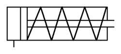
Pneumatic cylinder
In general, based on the application, a pneumatic cylinder is usually a single acting cylinder, where there is a single port in the cylinder and were cylinder extension is done by compressed air and retraction by means of open coiled spring. In double acting cylinders two ports both extend and retract by means of compressed air.
Direction control valve (DCV)
The direction control valve is used to control the direction of flow of compressed air. Usually classified into normally open (NO)and normally closed (NC)valves. The normally open valves will permit flow from inlet port of valve to outlet port normally the flow will be cut by changing the position of the valve. The normally closed valves will not permit flow from inlet port of valve to outlet port normally the flow will be permitted only by changing the position of the valve. In general valves are designated as 2/2 DCV, 3/2DCV, 5/2 DCV,5/3 DCV etc. In which the first numerical indicates number of ports and second numerical indicates number of positions. To change the position, the valves are generally actuated by:
Two pressure valve (And Valve)
Generally two valve actuators (push buttons) are used when both the push buttons are pressed at a time the air flow takes place if either any one is pressed at a time air flow will not take place in valve outlet. Generally used in mechanical press and machine tools to ensure operator's both the hands are outside the machine or press during operation.
OR Valve
Generally two valve actuators (push buttons) are used when either one push button is pressed the air flow takes place. This is also called as shuttle valve.
Check valve
The check valve allows air flow in one direction, it is also called as non return valve.
Quick exhaust valve
The valve construction is OR valve with exhaust port,ensures quick return of cylinder therefore cycle time reduces
Flow control valve
The combination throttle valve connected to check valve is called one way flow control valve, while air passes from one direction to other the check valve will not allow the air flow (As the check valve allows flow only in one direction) while through the restricted way of throttle compressed air flow takes place. While the air comes out from other way both the ways of throttle as well as the check valve opens to pass the compressed air therefore the piston moment in one direction can be controlled.
Time delay valve
The combination of 3/2 direction control valve, reservoir and flow control valve is time delay valve. This valve is used to delay the actuation of cylinder after pressing the push button or pedal etc.
Pressure relief valve
The pressure relief valve is used to maintain the system set pressure, in case if the system set pressure increases the pressure relief valve gets opens and exhaust the compressed air to atmosphere
The following devices operate using compressed gases, but are not normally thought of as being pneumatic circuits: