
 | ||
A piping and instrumentation diagram/drawing (P&ID) is a detailed diagram in the process industry which shows the piping and vessels in the process flow, together with the instrumentation and control devices.
Contents
Superordinate to the piping and instrumentation flowsheet is the process flow diagram (PFD) which indicates the more general flow of plant processes and equipment and relationship between major equipment of a plant facility.
Contents and function
A piping and instrumentation diagram/drawing (P&ID) is defined by the Institute of Instrumentation and Control as follows:
- A diagram which shows the interconnection of process equipment and the instrumentation used to control the process. In the process industry, a standard set of symbols is used to prepare drawings of processes. The instrument symbols used in these drawings are generally based on International Society of Automation (ISA) Standard S5.1
- The primary schematic drawing used for laying out a process control installation.
They usually contain the following information:
P&IDs are originally drawn up at the design stage from a combination of process flow sheet data, the mechanical process equipment design, and the instrumentation engineering design. During the design stage, the diagram also provides the basis for the development of system control schemes, allowing for further safety and operational investigations, such as a Hazard and operability study (HAZOP). To do this, it is critical to demonstrate the physical sequence of equipment and systems, as well as how these systems connect.
P&IDs also play a significant role in the maintenance and modification of the process after initial build. Modifications are red-penned onto the diagrams and are vital records of the current plant design.
They are also vital in enabling development of;
P&IDs form the basis for the live mimic diagrams displayed on graphical user interfaces of large industrial control systems such as SCADA and distributed control systems.
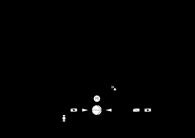
Symbols of chemical apparatus and equipment
Below are listed some symbols of chemical apparatus and equipment normally used in a P&ID, according to ISO 10628 and ISO 14617.