
 | ||
A Parshall flume, the most recognized and commonly used flume today, is a fixed hydraulic structure developed to measure surface waters and irrigation flow. It is currently used to measure volumetric flow rate in industrial discharges, municipal sewer lines, and influent/effluent flows in wastewater treatment plants. The Parshall flume accelerates flow through a contraction of both the parallel sidewalls and a drop in the floor at the flume throat. Under free-flow conditions the depth of water at specified location upstream of the flume throat can be converted to a rate of flow. Some states specify the use of Parshall flumes, by law, for certain situations (commonly water rights).
Contents
- Development
- Function
- Derivation
- Free Flow vs Submerged Flow
- Free flow E Y diagram depiction
- Parshall flume discharge values
- Example
- Construction
- Installation
- Drawbacks
- Variations
- Montana flume
- Short Section USGS Portable Parshall flume
- References
The design of the Parshall flume is standardized under ASTM D1941, ISO 9826:1992, and JIS B7553-1993. The flumes are not patented and the discharge tables are not copyright protected.
A total of 22 standard sizes of Parshall flumes have been developed, covering flow ranges from 0.005 cfs [0.1416 l/s] to 3,280 cfs [92,890 l/s].
Submergence transitions for Parshall flumes range from 50% (1”-3” sizes) to 80% (10’-50’ sizes), beyond which point level measurements must be taken at both the primary and secondary points of measurement and a submergence correction must be applied to the flow equations. It is important to note that the secondary point of measurement (Hb) for a Parshall flume is located in the throat, measuring Hb can be difficult as flow in the throat of the flume is turbulent and prone to fluctuations in the water level. 90% is viewed as the upper limit for which corrections for submerged flow are practical.
Under laboratory conditions Parshall flumes can be expected to exhibit accuracies to within +/-2%, although field conditions make accuracies better than 5% doubtful.
Development
Beginning in 1915, Dr. Ralph Parshall of the U.S. Soil Conservation Service altered the subcritical Venturi flume include a drop in elevation through the throat of the flume. This created a transition from subcritical flow conditions to supercritical flow conditions through the throat of the flume.
Modifications to the Venturi flume that Parshall made include:
in 1930, the improved flume was named the Parshall Measuring Flume by the Irrigation Committee of the American Society of Civil Engineers (ASCE) in recognition of Parshall's accomplishments. Parshall was additionally honored as a Life Member of the ASCE.
Function
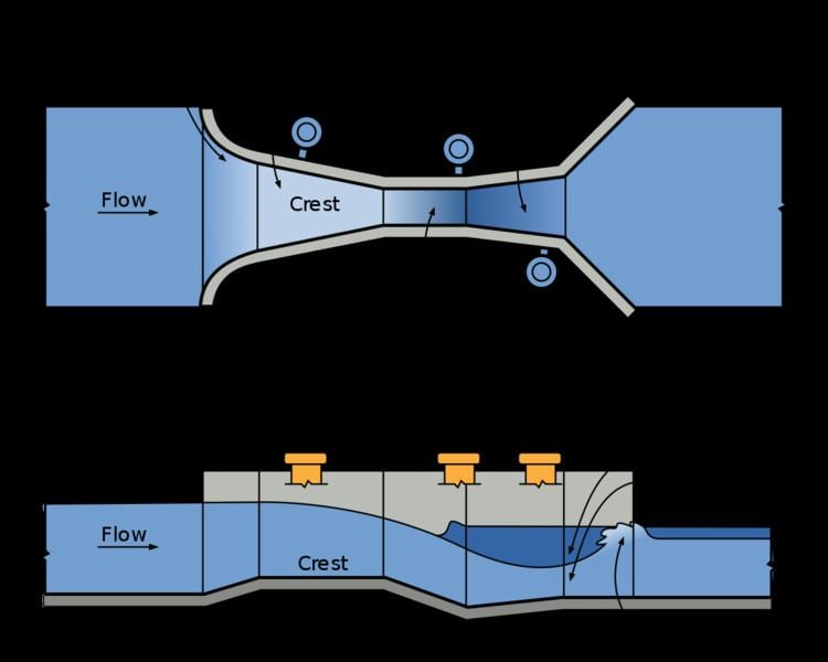
The Parshall Flume acts essentially as a constriction, a downward step, and then an expansion: the upstream section is uniformly converging and flat, the throat is a short parallel section that slopes downward, and the downstream section is uniformly diverging and slopes upward to an ending elevation that is less than the upstream starting elevation. The width of the throat determines the flume size; 22 standardized sizes have been developed, ranging from 1 in. to 50 ft. (0.005 ft3/s to 3,280 ft3/s).
There are two conditions of flow that can occur in a Parshall Flume: free flow and submerged flow. When free flow conditions exist, the user only needs to collect one head measurement (Ha, the primary point of measurement) to determine the discharge. For submerged flow a secondary head measurement (Hb) is required to determine the flume is submerged and the degree of submergence.
The primary point of measurement (Ha) is located in the inlet of the flume, two-thirds of the length of the converging section from the flume crest. The secondary point of measurement (Hb) is located in the throat of the flume.
A hydraulic jump occurs downstream of the flume for free flow conditions. As the flume becomes submerged, the hydraulic jump diminishes and ultimately disappears as the downstream conditions increasingly restrict the flow out of the flume.
The free-flow discharge can be summarized as
Where
Derivation
A Parshall Flume relies on the conservation of energy principle. The sum of the kinetic and potential energy at a given point must be equal to the energy at any other point along the stream. The total energy or “head” must be equal. Using the equations, we will solve for Q.
Where E1 is the energy at Ha, E2 at the flume crest, and E3 at Hb respectively. Since E2 is located at the flume crest where there is a steep drop, critical flow conditions occur.
Rearranging and substituting in the above equations, we get
Or
Since we know that Q = v⋅y⋅b and v = √(gyc) at critical depth, we can use these relationships to solve for the discharge.
Broken further down, we realize that
And
Since this is measured upstream, where flow is sub-critical, it can be stated that y1 ≫ v2/2g
Therefore, for a rough approximation we can say
This equation simplifies to:
These final two equations are very similar to the Q = CHan equations that are used for Parshall Flumes. In fact when looking at the flume tables, n has a value equal to or slightly greater than 1.5, while the value of C is larger than (3.088 b2) but still in a rough estimation. It should be noted that the derived equations above will always underestimate actual flow since both the derived C and n values are lower than their respective chart values.
For the Parshall Flume equation used to calculate the flow rate, both empirical values C and n are known constants (with various values for each Parshall Flume size) leaving Ha (depth upstream) as the only variable needing to be measured. Likewise, in the energy conservation equation, y1 (or the depth of flow) is needed.
Free Flow vs. Submerged Flow
Free Flow – when there is no “back water” to restrict flow through a flume. Only the upstream depth needs to be measured to calculate the flow rate. A free flow also induces a hydraulic jump downstream of the flume.
Submerged Flow – when the water surface downstream of the flume is high enough to restrict flow through a flume, submerged flume conditions exist. A backwater buildup effect occurs in a submerged flume. For a flow calculation a depth measurement both upstream and downstream is needed.
Although commonly thought of as occurring at higher flow rates, It should be noted that submerged flow can exist at any flow level as it is a function of downstream conditions. In natural stream applications, submerged flow is frequently the result of vegetative growth on the downstream channel banks, sedimentation, or subsidence of the flume.
Free flow E-Y diagram depiction
Illustrated above is a unitless E – Y diagram and how Energy and depth of flow changes throughout a Parshall Flume. The two blue lines represent the q values, q1 for the flow before the constriction, and q2 representing the value at the constriction (q = Q/b= ft2/s, or flow over width in a rectangular channel). When a constriction (decrease in width) happens Between E1 and E2, the q value changed (and becomes the new critical depth), while the energy remains the same. Then the flume experiences a downward step which results in a gain in energy. This gain in energy is equal to the size of the step (or Δz). From this the principles of conservation of energy are used to develop a set of calculations to predict the flow rate.
Parshall flume discharge values
For free flow, the equation to determine the flow rate is simply Q = CHan where:
(See Figure 1 above)
Parshall flume discharge table for free flow conditions:
Table 1
For submerged flow, a depth of flow needs to be taken upstream (Ha) and downstream (Hb). See locations of Ha and Hb in Figure 1.
Table 2
If Hb/Ha is greater or equal to St then it is a submerged flow. If there is submerged flow, adjustments need to be made in order for the Parshall Flume to work properly.
The discharge (Q) can be found using the following equations and table:
Where:
(Note: All various Q values are in ft3/s, Ha is in feet, and M varies in units)
Table 3
Example
Parshall Flume Free Flow Example Problem:
Using the Parshall Flume free flow equation, determine the discharge of a 72 inch flume with a depth, Ha of 3 feet.
From Table 1: Throat Width C n 72 in = 6 ft 24 1.59
So if there is a depth of 3 feet, the flow rate is ≈ 140 ft3/s
Approximate the discharge using the derived discharge equation shown above (Equation 5). This equation was derived using the principles of specific energy and is only to serve as an estimate for the actual discharge of the Parshall Flume. Again, it should be noted that equations 5 and 6 will always underestimate the actual flow since both the derived C and n values are lower than their respective empirically derived chart values.
Parshall flume submerged flow example problem:
Using the Parshall Flume flow equations and Tables 1-3, determine the flow type (free flow or submerged flow) and discharge for a 36 inch flume with an upstream depth, Ha of 1.5 ft and a downstream depth, Hb of 1.4 ft. For reference of locations Ha and Hb, refer to Figure 1.
From Table 2, the Parshall Flume submergence transition (St) for a 36 inch = 3 feet flume is 0.7. Since Hb/Ha is greater than or equal to 0.7, it is a submerged flow.
Qnet = Qfree flow – Qcorrection
Q = CHan From Table 1: Throat Width C n 36 in = 3 ft 12 1.57 Qfree flow = 12(1.5 ft)1.57 = 22.68 ft3/s
Qcorrection = M (0.000132 Ha2.123 e9.284 S) Where S = Hb/Ha = 1.4 ft/1.5 ft = 0.93 From Table 3, M = 2.4 for a flume size of 3 ft Qcorrection = 2.4(0.000132(1.5 ft)2.123e9.284(0.93)) = 4.21 ft3/s
Qnet = 22.68 ft3/s – 4.21 ft3/s = 18.5 ft3/s
Construction
A wide variety of materials are used to make Parshall flumes, including:
Smaller Parshall flumes tend to be fabricated from fiberglass and galvanized steel (depending upon the application), while larger Parshall flumes tend to fabricated from fiberglass (sizes up to 144") or concrete (160"-600").
By the 1960's several different companies began to commercially offer Parshall flumes. These manufacturers have typically produce flumes from one type of material only (typically fiberglass/grp or steel), although currently a few, such as Openchannelflow, offer Parshall flumes in a variety of materials.
Installation
Dr. Parshall's initial focus was for the use of his namesake flume to measure flows in irrigation channels and other surface waters.
Over time, however, the Parshall flume has proven to be applicable to a wide variety of open channel flows including:
Drawbacks
Variations
Two variations of the Parshall flume have been developed over time: the Montana flume and the Short Section (USGS / Portable) Parshall flume.
Montana flume
The Montana flume omits the throat and discharge sections of the Parshall. By omitting these sections, the flume is shortened by more than half, while retaining the free-flow characteristics of the same-size Parshall. With the deletion of the throat and discharge section, the Montana flume has little resistance to submersion and, like the H flume, should be used where free-spilling discharge is present under all flow conditions. The Montana flume is described in US Bureau of Reclamation's Water Measurement Manual and two technical standards MT199127AG and MT199128AG by Montana State University (note that Montana State University has currently withdrawn both standards for updating/review).
Short Section (USGS Portable) Parshall flume
The short-section Parshall (sometimes referred to as a USGS or Portable Parshall) omits the discharge section of the flume. Originally designed by Troxell and Taylor in 1931 and published under "Venturi Flume" as a memorandum from the office of the Ground Water Branch, USGS, the design was again brought to the attention of potential users in Taylors' paper "Portable Venturi Flume for Measuring Small Flows in 1954. This modification - supplied by the USGS Hydrologic Instrumentation Facility - is available in two sizes: the original 3" and the recently added 6".
Kilpatrick notes that the discharge for this modification of the Parshall flume is slightly greater than for a standard Parshall flume of the same size. This has been attributed to potential manufacturing tolerance variations rather than the actual operation of the flume itself and users are cautioned to verify the flume's dimensions before proceeding with data collection. As with any Parshall flume, flumes varying from the standard dimensions flumes should be individual rated.
When used for stream gauging, aluminum is the typical material of construction - primarily due to its light weight.