
 | ||
Orbital Replacement Units (ORUs) are key elements of the International Space Station that can be readily replaced when the unit either passes its design life or fails. Examples of ORUs are: pumps, storage tanks, controller boxes, antennas, and battery units. Such units are replaced either by astronauts during EVA or by the Dextre (SPDM) robotic arm. All are stored on the three External Stowage Platforms (ESPs) or the four ExPRESS Logistics Carriers (ELCs) mounted on the Integrated Truss Structure (ITS).
Contents
Introduction
While spare parts/ORUs were routinely brought up and down during the ISS life-time via Space Shuttle resupply missions, there was a heavy emphasis once the Station was considered complete.
Several Shuttle missions were dedicated to the delivery of ORUs using support carrier structures/pallets of which some remained in the cargo bay, some that were deployed and retrieved and other pallets that were designed to be removed from the payload bay by RMS and placed onto the station.
Deployable pallet flights included STS-102 with External Stowage Platform ESP-1, STS-114 with ESP-2, STS-118 with ESP-2, STS-129 with ExPRESS Logistics Carrier ELC-1 and ELC-2, STS-133 with ELC-4 and STS-134 with ELC-3.
Other modes of ORU delivery included:
Payload bay sidewall mounted ORUs, such as BCDUs, were regularly carried and transported to the ISS via EVAs.
Also, three flights of the Integrated Cargo Carrier (ICC) which remained in the cargo bay on flights STS-102, STS-105 and STS-121; one use of the ICC-Lite on STS-122 (a shortened version of the ICC); two uses of the ICC-Vertical Light Deployable on STS-127 as ICC-VLD and STS-132 as ICC-VLD2, which were deployed and retrieved during the mission; and five uses of the Lightweight MPESS Carrier (LMC) on STS-114, STS-126, STS-128, STS-131 and STS-135, the LMC was not designed to be deployed and remained in the shuttle payload bay throughout the flight.
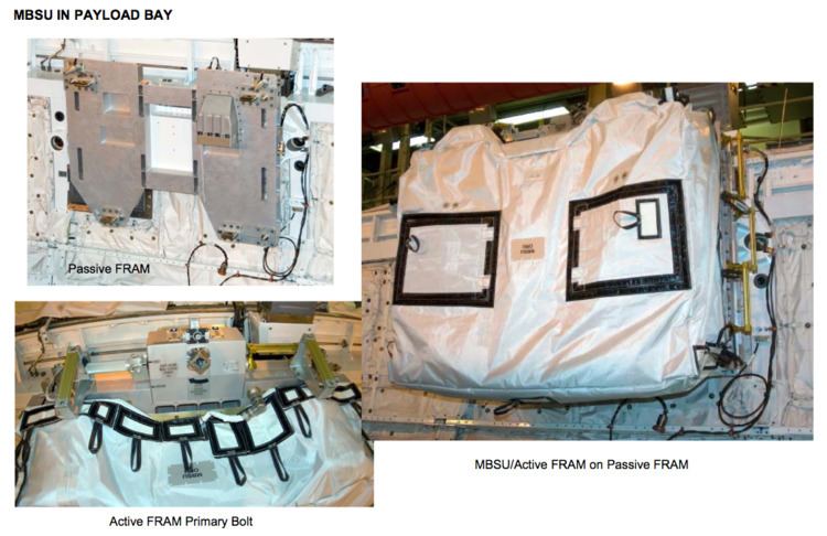
To date other than the Space Shuttle missions, only one other mode of transportation of ORUs was utilised by the station, the Japanese cargo vessel HTV-2 delivered an FHRC and CTC-4 via its Exposed Pallet (EP), and HTV-4 delivered a Main Bus Switching Unit (MBSU) and a Utility transfer assembly (UTA).
Types of ORUs
Orbital replacement units are parts of the main systems and subsystems of the external elements of the ISS. Affecting the control of the cooling system, the movement and control of the solar arrays and SARJ as well as the flow of power throughout the station from solar arrays to the heat rejection system as part of the External Active Thermal Control System (EATCS). As well as storage tanks for oxygen as part of the station Environmental Control and Life Support System (ECLSS). ORUs, can be hardware such as radiators, or simply batteries or communication antennas. Essentially any element that can readily be removed and replaced when required.
The replaceable modular nature of the station allows its life to be extended well beyond its initial design life, theoretically.
ORUs and robotic arms
ORUs to be handled by Dextre have attachments designed to be gripped with the ORU/Tool Changeout Mechanisms on the end of each arm. The H‐fixture is for massive objects, the most common is a Micro‐fixture(also known as a Micro‐square) and the Micro‐Conical Fitting is used in tight spaces. A Modified Truncated Cone(MTC) Target is used to visually line up Dexter's arm to grab a fixture. Any ORU with a grapple fixture can be moved by the Canadarm2.
Multiple spares
Three spares – ESP-2 FRAM-7 (keel side) FHRC SN1003, ESP-3 FRAM-2 (top side) FHRC SN1004, ELC-4 FRAM-5 (keel side) FHRC SN0005 delivered by HTV-2.
Four original spares (two unused Pump Modules remain) - ELC-1 FRAM-7 (keel side) PM SN0007, ELC-2 FRAM-6 (keel side) PM SN0005 Two utilised - ESP-2 FRAM-1 (top side) PM SN0004 (was installed here during STS-121, then removed by the Exp 24 crew to replace the failed original PM SN0002 on the S1 truss. That failed unit was returned to earth by the STS-135 crew); ESP-3 FRAM-3 (top side) PM SN0006 (was swapped with failed PM SN0004 from S1 truss by Exp 38 crew Dec. 2013, then stored on the MT POA). The ISS-41 EVA-27 crew relocated this unit from the POA to ESP-2 FRAM-1 in Oct. 2014.
Two spares – ELC-1 FRAM-9 (keel side), ELC-3 FRAM-5 (keel side) Also note - other than these two spares, two other Shuttle missions brought up new ATAs and then returned the failed ATAs: STS-128 ATA SN0004 up/SN0002 down (P1 truss original ATA) and STS-131 SN0002 up/SN0003 down (S1 truss original ATA).
Two spares – ELC-1 FRAM-6 (keel side) NTA SN0002 (refurbished) ELC-2 FRAM-9 (keel side) NTA SN0003 (refurbished) Also note - other than these two spares, two other Shuttle missions replaced NTAs. STS-122 delivered new NTA SN0004 and then returned the depleted P1 Truss NTA SN0003. STS-124 swapped the new NTA SN0005 from ESP-3 FRAM 2 with the depleted NTA SN0002 from the S1 Truss. The STS-126 crew returned this depleted NTA.
One spare – ELC-3 FRAM-6 (keel side), one depleted tank ELC-2 FRAM-4 (top side) Note the depleted tank was swapped with the original HPGTA launched on ELC-2 at FRAM-4.
Three units – CTC-3 formerly on ELC-2 FRAM-2 (top side), was later moved to ESP-2 FRAM-3 via SPDM. CTC-2 on ELC-4 FRAM-2 (keel side), CTC-5 on ELC-3 FRAM-1 (top side)
Two spares – ESP-3 FRAM-1 (top side), ESP-2 FRAM-5 (keel side)
Two spares – ELC-1 FRAM-5 (top side) CMG SN104, ELC-2 FRAM-5 (top side) CMG SN102 Note: STS-118 crew delivered a CMG on ESP-3, swapping it for a failed unit on the ITS-Z1 truss. That failed unit was placed on ESP-2 FRAM-5 until it was returned by STS-122.[12]
Two spares – ELC-3 FRAM-4 (top side), ELC-3 FRAM-7 (keel side)
Three spares – ESP-1 FRAM-2, ESP-2 FRAM-2 (top side), ELC-2 FRAM-2 (top side)
Two spares – ESP-3 FRAM-6 (keel side), ELC-1 FRAM-4 (top side)
Two spares – ESP-2 FRAM-4 (top side), ELC-2 FRAM-7 (placed via SPDM, delivered by HTV-4 Aug. 2013). The MBSU on ESP-2 FRAM-6 (keel side) was added by STS-120 crew, then swapped with a failed unit from the S0 truss by the Exp 32 crew in late 2012.
Two spares - ESP-2 FRAM-8 (keel side) ELC-4 FRAM-4 (keel side) Utility Transfer Assembly (delivered by HTV-4 EP via SPDM Aug. 2013)
Five original spares, now Four spares - ESP-1 FRAM-1 Plus the original 4 spares, 2 on ITS-S6, 2 on ITS-P6, one of which was swapped out for a faulty unit during an Exp 35 EVA May 11, 2013.
Single spares
The TUS reel assembly (TUS-RA) is basically a large spool much like a garden hose reel that pays out cable when the MT moves away and rolls it back up as the MT returns to the center of the truss. This is the same TUS-RA retrieved during STS-121. It was replaced and this failed unit was returned to earth and refurbished to later fly on ELC-2.
The SSRMS has two identical grapple end points called LEE that enable it to reattach either end to the station as its new base.
The Heat Rejection Subsystem (HRS) consists of a base, eight panels, torque panel, torque arm, an interconnected fluid system, a scissors-type deployment mechanism and a computer controlled motor/cable deployment system. Part of the station’s external active thermal control system (EATCS), the HRS radiator rejects thermal energy via radiation.
The LDU provides drive and stopping forces for the mobile transporter along the integrated truss structure rail.
Plasma Contactor Unit (PCU) is used to disperse the electrical charge that builds up by providing an electrically conductive “ground path” to the plasma environment surrounding the ISS. This prevents the electrical discharges and provides a means of controlling crew shock hazard during EVA. There are two PCUs located on the ISS Zenith 1 Truss, both of which are operated during EVA.