
 | ||
Optimisation of cutting cycles in conventional underground coal sections to improve productivity serves as an area of study that deals with the utilisation of the machines in conventional underground coal sections. Utilisation of machines focuses on reducing the time that machines spend idle and increasing the amount of time during shifts that machines are actively contributing to production. This can be addressed through effective planning of the cutting cycle parameters or by adjusting the design of machines to modify the cutting cycles
Contents
Conventional coal mining
Conventional underground coal mining relies upon the use of continuous miners in order to extract coal reserves from underground coal seams. In combination with the continuous miners, shuttle cars are used to transport the extracted coal from the face to a transfer point (feeder breaker). From there the coal is typically tipped onto the underground conveyor system, which transports the coal to the surface in order to be distributed to customers. Effective management of the cutting, loading and tipping cycles utilised in the sections serve as a possible area for productivity improvement.
One-directional cutting cycle
A one-directional cutting cycle currently utilised in underground coal sections progresses as follows:
The cutterhead in the case of the above-mentioned cutting cycle always shears from the roof down to the floor. By adjusting the parameters relating to the above-mentioned cutting cycle, the utilisation of the available production times can be improved.
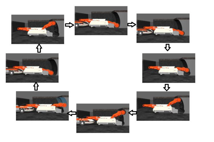
Modified bi-directional cutting cycle
The design of modern machines is continuously improving and the introduction of machines that have the ability to shear upwards has led to the option to modify the typical cutting cycle in an attempt to improve the productivity of conventional underground coal sections. The utilisation of the Sandvik MC 470 machine is an example of an instance where the operation of the machine enables the utilisation of a more productive cutting cycle. This is accomplished by enabling the machine to shear both down and up by sumping the cutterhead near the floor and near the roof, respectively. The modified cutting cycle typically progresses as follows:
Key performance indicators
Number of shuttle car loads is defined as the total number of fully loaded shuttle cars that were loaded at the continuous miner and subsequently tipped at the feeder breaker. Average shuttle car load time refers to the average time in seconds that was necessary to load a shuttle car to its maximum coal-carrying capacity. Average shuttle car change time refers to the average time in seconds that was necessary for an unloaded shuttle car to be repositioned behind the continuous miner after the previously loaded shuttle car trammed away from the machine towards the tipping point. Conveyor on time refers to the total time in minutes that the flight chain conveyor on the continuous miner was running. Cutter ON - Conveyor OFF - bunker operation [min]– bunker operation refers to the total time in minutes that ONLY the cutterhead was running and coal was being stored on the spade. Shuttle car away time refers to the total time in minutes that was utilised by a loaded shuttle car to travel from the continuous miner to the feeder breaker, tip the loaded coal and travel back to the continuous miner to be loaded again. Cutter operation time refers to the total time in minutes that the cutterhead was running. Relocation time refers to the total time in minutes that was utilised in order to relocate a continuous miner to a different heading after the maximum allowable unsupported length of the previously cut heading was reached. Utilisation of the modified cutting cycle has improved the general consistency of the production machines in achieving the target values of the key performance indicators. This is confirmed by means of continuous production reporting that monitors and documents the key performance indicators on a shift basis. The following table shows an example of a typical summary of key performance indicators and the actual numbers achieved. It is illustrative of the success with which the bi-directional cutting cycle is being run at a South African coal mine.
From these figures it is clear that the number of shuttle car loads is significant and above target. The shuttle car change time is also significantly impacted.
Cutting cycle comparison
In order to justify the selection and utilisation of the bi-directional cutting cycle a comparison is to be made between the one-directional and bi-directional cutting cycle. Different Key performance indicators are utilised by different companies to quantify the performance of machines operating in production sections. The most appropriate figure to be utilised in the justification of the bi-directional cutting cycle is the tons per hour figure. The increase in the production rate due to the improved cutting cycle serves as the differentiating figure. Through analysis of several production reports from South African coal mines, the following comparative figures were obtained for the two cutting cycles.
From the above-mentioned averages obtained from production reports it is clear that the bi-directional cutting cycle maintains a larger average production rate. This increase in the production rate serves as the justification of the utilisation of the improved cutting cycle and illustrates the value of the consideration of manageable and adjustable elements of the production process in conventional underground coal mine sections.