
 | ||
In power engineering, nodal admittance matrix (or just admittance matrix) or Y Matrix or Ybus is an N x N matrix describing a power system with N buses. It represents the nodal admittance of the buses in a power system. In realistic systems which contain thousands of buses, the Y matrix is quite sparse. Each bus in a real power system is usually connected to only a few other buses through the transmission lines. The Y Matrix is also one of the data requirements needed to formulate a power flow study.
Contents
Context
Electric power transmission needs optimization in order to determine the necessary real and reactive power flows in a system for a given set of loads, as well as the voltages and currents in the system. Power flow studies are used not only to analyze current power flow situations, but also to plan ahead for anticipated disturbances to the system, such as the loss of a transmission line to maintenance and repairs. The power flow study would determine whether or not the system could continue functioning properly without the transmission line. Only computer simulation allows the complex handling required in power flow analysis because in most realistic situations the system is very complex and extensive and would be impractical to solve by hand. The Y Matrix is a tool in that domain. It provides a method of systematically reducing a complex system to a matrix than can be solved by a computer program. The equations used to construct the Y matrix come from the application of Kirchhoff’s current law and Kirchhoff’s voltage law to a circuit with steady-state sinusoidal operation. These laws give us that the sum of currents entering a node in the circuit is zero, and the sum of voltages around a closed loop starting and ending at a node is also zero. These principles are applied to all the nodes in a power flow system and thereby determine the elements of the admittance matrix, which represents the admittance relationships between nodes, which then determine the voltages, currents and power flows in the system.
Construction
Starting from the single line diagram of a power system, there are three main steps before writing the equations that form the
It is important to note that
Once the admittance matrix has been formed, the admittance matrix can be input to solve the matrix form of Ohm's Law--the equation
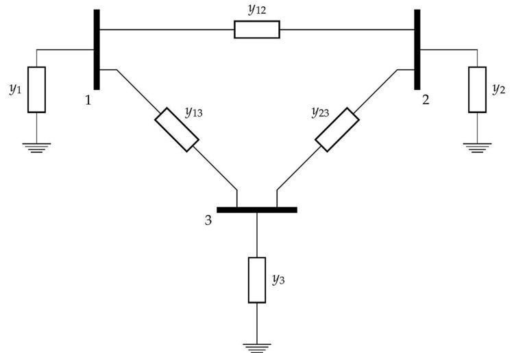
To illustrate this process with the admittance matrix of the three bus network in the figure would be:
The Y Matrix diagonal elements
For small transmission systems of about less than 10 nodes or buses, the Y matrix can be calculated manually. But for a realistic system with relatively large number of nodes or buses, say 1000 nodes, a computer program for computing Y is more practical to use.
To help motivate the importance of using a system of equations in matrix form, see the adjacent figure. Not only does it become impractical to calculate the current vector
Example:
To take a look at a generalizable