 | ||
In digital electronics, a NAND gate (negative-AND) is a logic gate which produces an output which is false only if all its inputs are true; thus its output is complement to that of the AND gate. A LOW (0) output results only if both the inputs to the gate are HIGH (1); if one or both inputs are LOW (0), a HIGH (1) output results. It is made using transistors and junction diodes. By De Morgan's theorem, AB=A+B, and thus a NAND gate is equivalent to inverters followed by an OR gate.
Contents
The NAND gate is significant because any boolean function can be implemented by using a combination of NAND gates. This property is called functional completeness. It shares this property with the NOR gate.
Digital systems employing certain logic circuits take advantage of NAND's functional completeness.
The function NAND(a1, a2, ..., an) is logically equivalent to NOT(a1 AND a2 AND ... AND an).
Symbols
There are three symbols for NAND gates: the MIL/ANSI symbol, the IEC symbol and the deprecated DIN symbol sometimes found on old schematics. For more information see logic gate symbols. The ANSI symbol for the NAND gate is a standard AND gate with an inversion bubble connected.
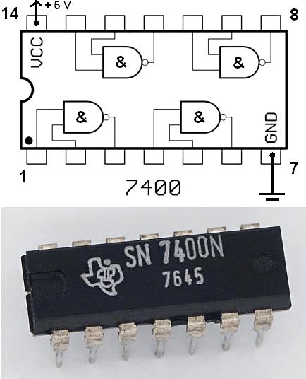
Hardware description and pinout
NAND gates are basic logic gates, and as such they are recognised in TTL and CMOS ICs.
Implementations
The NAND gate has the property of functional completeness. That is, any other logic function (AND, OR, etc.) can be implemented using only NAND gates. An entire processor can be created using NAND gates alone. In TTL ICs using multiple-emitter transistors, it also requires fewer transistors than a NOR gate.
