
 | ||
In Electrical Engineering modified nodal analysis or MNA is an extension of nodal analysis which not only determines the circuit's node voltages (as in classical nodal analysis), but also some branch currents. Modified nodal analysis was developed as a formalism to mitigate the difficulty of representing voltage-defined components in nodal analysis (e.g. voltage-controlled voltage sources). It is one such formalism. Others, such as sparse tableau formulation, are equally general and related via matrix transformations.
Contents
Method
The MNA uses the element's branch constitutive equations or BCE, i.e., their voltage - current characteristic and the Kirchhoff's circuit laws. The method is often done in four steps, but it can be reduced to three:
Step 1
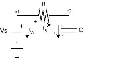
Write the KCL of the circuit. At each node of an electric circuit one writes the currents coming in and out of the node. Take care however in the MNA the current of the independent voltage sources is taken from the "plus" to the "minus". See Figure 1. Also note that the right hand side of each equation is always equal to zero. So that the branch currents that come into the node are given a negative sign, whereas the branch currents coming out are given a positive sign.
Step 2
Use the BCE in terms of the node voltages of the circuit to eliminate as many branch currents as possible. Writing the BCE's in terms of the node voltages saves one step. If the BCE's were written in terms of the branch voltages, one more step, i.e., replacing the branches voltages for the node ones, would be necessary. In this article the letter "e" is used to name the node voltages, while the letter "v" is used to name the branch voltages.
Step 3
Finally, write down the unused equations.
Example
The figure shows a RC series circuit and the table shows the BCE of a linear resistor and a linear Capacitor. Note that in the case of the resistor the admittance
Step 1
In this case there are two nodes,
At node e1 the KCL yields:
and at node e2:
Step 2
With the provided BCEs in the table and observing that:
the following equations are the result:
Step 3
Note that at this point there are two equations but three unknowns. The missing equation comes from the fact that
and so finally we have three equations and three unknowns, that leads to a solvable linear system.
Modified Nodal Analysis and DAEs
If the vector
where
This is a linear differential algebraic equation (DAE), since
Non-smooth analysis
DAEs assume smooth characteristics for individual components; for example, a diode can be modeled/represented in a MNA with DAEs via the Shockley equation, but one cannot use an apparently simpler (more ideal) model where the sharply exponential forward and breakdown conduction regions of the curve are just straight vertical lines. Circuit analysis (including MNA) with the latter kind of equations is actually more involved (than using DAEs) and is the topic of non-smooth dynamical systems (NSDS) analysis, which relies on the theory of differential inclusions.