
 | ||
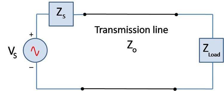
Mismatch loss in transmission line theory is the amount of power expressed in decibels that will not be available on the output due to impedance mismatches and signal reflections. A transmission line that is properly terminated, that is, terminated with the same impedance as that of the characteristic impedance of the transmission line, will have no reflections and therefore no mismatch loss. Mismatch loss represents the amount of power wasted in the system. It can also be thought of as the amount of power gained if the system was perfectly matched. Impedance matching is an important part of RF system design; however, in practice there will likely be some degree of mismatch loss. In real systems, relatively little loss is due to mismatch loss and is often on the order of 1dB.
Contents
Calculation
Mismatch loss (ML) is the ratio of incident power to the difference between incident and reflected power:
where
The fraction of incident power delivered to the load is
where
If the reflection coefficient is known, mismatch can be calculated by
In terms of the voltage standing wave ratio (VSWR):
Mismatch error
If there are two or more components in cascade as is often the case, the resultant mismatch loss is not only due to the mismatches from the individual components, but also from how the reflections from each component combine with each other. The overall mismatch loss cannot be calculated by just adding up the individual loss contributions from each component. The difference between the sum of the mismatch loss in each component and total mismatch loss due to the interactions of the reflections is known as mismatch error. Depending on how the multiple reflections combine, the overall system loss may be lower or higher than the sum of the mismatch loss from each component. Mismatch error occurs in pairs as the signal reflects off of each mismatched component. So for the example in Figure 3, there are mismatch errors generated by each pair of components. The mismatch uncertainty increases as the frequency increases, and in wide-band applications. The phasing of the reflections makes it particularly harder to model.
The general case for calculating mismatch error (ME) is:
where