
 | ||
M.2 (pronounced M dot two), formerly known as the Next Generation Form Factor (NGFF), is a specification for internally mounted computer expansion cards and associated connectors. It replaces the mSATA standard, which uses the PCI Express Mini Card physical card layout and connectors. M.2's more flexible physical specification allows different module widths and lengths, and, paired with the availability of more advanced interfacing features, makes the M.2 more suitable than mSATA for solid-state storage applications in general and particularly for the use in small devices such as ultrabooks or tablets.
Contents
Computer bus interfaces provided through the M.2 connector are PCI Express 3.0 (up to four lanes), Serial ATA 3.0, and USB 3.0 (a single logical port for each of the latter two). It is up to the manufacturer of the M.2 host or device to select which interfaces are to be supported, depending on the desired level of host support and device type. The M.2 connector has different keying notches that denote various purposes and capabilities of M.2 hosts and modules, preventing plugging of M.2 modules into feature-incompatible host connectors.
In addition to supporting legacy Advanced Host Controller Interface (AHCI) at the logical interface level, M.2 specification also supports NVM Express (NVMe) as the logical device interface for M.2 PCI Express SSDs. While the support for AHCI ensures software-level backward compatibility with legacy SATA devices and legacy operating systems, NVM Express is designed to fully utilize the capability of high-speed PCI Express storage devices to perform many I/O operations in parallel.
Features
Buses exposed through the M.2 connector are PCI Express 3.0, Serial ATA (SATA) 3.0 and USB 3.0, which is backward compatible with USB 2.0. As a result, M.2 modules can integrate multiple functions, including the following device classes: Wi-Fi, Bluetooth, satellite navigation, near field communication (NFC), digital radio, Wireless Gigabit Alliance (WiGig), wireless WAN (WWAN), and solid-state drives (SSDs). The SATA revision 3.2 specification, in its gold revision as of August 2013, standardizes the M.2 as a new format for storage devices and specifies its hardware layout.
The M.2 specification provides up to four PCI Express lanes and one logical SATA 3.0 (6 Gbit/s) port, and exposes them through the same connector so both PCI Express and SATA storage devices may exist in form of M.2 modules. Exposed PCI Express lanes provide a pure PCI Express connection between the host and storage device, with no additional layers of bus abstraction. PCI-SIG M.2 specification, in its revision 1.0 as of December 2013, provides detailed M.2 specifications.
There are three options available for the logical device interfaces and command sets used for interfacing with M.2 storage devices, which may be used depending on the type of M.2 storage device and available operating system support:
Form factors and keying
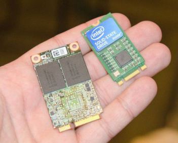
The M.2 standard has been designed as a revision and improvement to the mSATA standard, with the possibility of larger printed circuit boards (PCBs) as one of its primary incentives. While the mSATA took advantage of the existing PCI Express Mini Card (Mini PCIe) form factor and connector, M.2 has been designed from the ground up to maximize usage of the PCB space while minimizing the module footprint. As the result of the M.2 standard allowing longer modules and double-sided component population, M.2 SSD devices can provide larger storage capacities and can also double the storage capacity within the footprints of mSATA devices.
M.2 modules are rectangular, with an edge connector on one side (75 positions with up to 67 pins, 0.5 mm pitch, pins overlap on different sides of the PCB), and a semicircular mounting hole at the center of the opposite edge. Each pin on the connector is rated for up to 50 V and 0.5 A, while the connector itself is specified to endure up to 60 mating cycles. The M.2 standard allows module widths of 12, 16, 22 and 30 mm, and lengths of 16, 26, 30, 38, 42, 60, 80 and 110 mm. Initial line-up of the commercially available M.2 expansion cards is 22 mm wide, with varying lengths of 30, 42, 60, 80 and 110 mm.
Example codes: 2242 - 22mm wide, 42mm long, 2280 - 22mm wide, 80mm long.
An M.2 module is installed into a mating connector provided by the host's circuit board, and a single mounting screw secures the module into place. Components may be mounted on either side of the module, with the actual module type limiting how thick the components can be; the maximum allowable thickness of components is 1.5 mm per side. Different host-side connectors are used for single- and double-sided M.2 modules, providing different amounts of space between the M.2 expansion card and the host's PCB. Circuit boards on the hosts are usually designed to accept multiple lengths of M.2 modules, which means that the sockets capable of accepting longer M.2 modules usually also accept shorter ones by providing different positions for the mounting screw.
PCB of an M.2 module provides a 75-position edge connector; depending on the type of module, certain pin positions are removed to present one or more keying notches. Host-side M.2 connectors (sockets) may populate one or more mating key positions, determining the type of modules accepted by the host; as of April 2014, host-side connectors are available with only one mating key position populated (either B or M). Furthermore, M.2 sockets keyed for SATA or two PCI Express lanes (PCIe ×2) are referred to as "socket 2 configuration" or "socket 2", while the sockets keyed for four PCI Express lanes (PCIe ×4) are referred to as "socket 3 configuration" or "socket 3".
For example, M.2 modules with two notches in B and M positions use up to two PCI Express lanes and provide broader compatibility at the same time, while the M.2 modules with only one notch in the M position use up to four PCI Express lanes; both examples may also provide SATA storage devices. Similar keying applies to M.2 modules that utilize provided USB 3.0 connectivity.
Various types of M.2 devices are denoted using the "WWLL-HH-K-K" or "WWLL-HH-K" naming schemes, in which "WW" and "LL" specify the module width and length in millimeters, respectively. The "HH" part specifies, in an encoded form, whether a module is single- or double-sided, and the maximum allowed thickness of mounted components; possible values are listed in the right table above. Module keying is specified by the "K-K" part, in an encoded form using the key IDs from the left table above; it can also be specified as "K" only, if a module has only one keying notch.
Beside socketed modules, the M.2 standard also includes the option for having permanently soldered single-sided modules.
M.2 sockets with an "E" slot support Dual-Band Wireless LAN/Bluetooth cards (2230 or 1216). http://www.intel.com/content/dam/www/public/us/en/documents/product-briefs/dual-band-wireless-ac-8265-brief.pdf