
 | ||
The Lysekil project is an ongoing wave power project which is run by the Centre for Renewable Electric Energy Conversion at Uppsala University in Sweden.
Contents
Introduction
The main characteristic of the interaction between waves and a WEC (wave energy converter) is that energy is converted at large forces and low velocities due to the characteristic of ocean waves. As conventional generators are designed for high speed rotational motion, traditional wave power take-off system use a number of intermediate steps, for example hydraulics or turbines, to convert this slow-moving wave motion making it suitable for these generators.
Another way to tackle the problem; instead of adapting the waves to the power-take off system is adapting the system to the waves. This can be done by using a direct driven WEC (wave energy converter) with a linear generator. The advantage with this setup is a less complex mechanical system with potentially a smaller need for maintenance. One drawback with this kind of system is a more complicated transmission of the power to the grid. This is due to the characteristics of the generated voltage which will vary both in amplitude and frequency.
In the Lysekil project one goal was to develop a simple and robust wave energy system with a low need for maintenance. The approach was to find a system with few moving parts and as few energy converting steps as possible. Because of these requirements, a concept with a direct driven permanent magnet linear generator driven by a buoy that follows the motion at the sea surface was chosen. [1]
Purpose of the project
The Lysekil research project was established with the purpose to evaluate the chosen concept. The behavior of the WEC will be studied both when it works as a single unit and together with several other WECs as a part of a cluster. Other important aspects are the design of the transmission system, in other words, how the power is transported to the grid and how this affects other part of the system, such as the buoy absorption. Another purpose with the project is to determine the WEC’s environmental impact focusing on marine organisms, ranging from small bottom dwelling organism living in the seabed, from organism involving in biofouling to vertebrates.
Lysekil Research site
The test site is located on the Swedish west coast about 100 km north of Gothenburg, close to Lysekil. The site is located 2 km offshore and covers an area of 40 000 m2. The seabed in the area has an even surface with a slight incline towards west and the depth ranges from 24 m in the eastern part to 25 m in the west. The seabed consists mainly of sandy silt and some smaller areas are also covered with rougher material. The area will contain ten buoys connected to generators and an additional numbers of buoys for environmental impact studies. The permits allow the studies to go on to the end of 2013, then all equipment has to be removed unless a prolongation is applied for and approved.
The average energy flux at the research site during 2007, excluding August, was 3.4 kW/m. The most frequent sea state is characterized by an energy period, TE, around 4 sec and significant wave height Hs less than 0.5 m. The main energy contribution comes from the more energetic (but not that frequent) sea states.
Concept
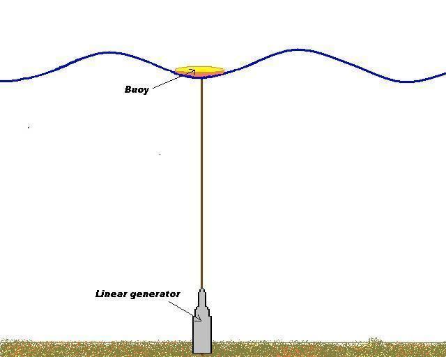
The wave power concept in the Lysekil project is based on a three phase permanent magnetized linear generator placed on the seabed. The generator is connected to a point absorbing buoy at the surface via a line. When the waves move the hydrodynamic action forces the buoy to move in a heaving motion. The movements of the buoy will then drive the translator in the generator, consequently inducing current in the stator windings. The translator is connected to the generator foundation with springs that retract the translator in the wave troughs.
The technology of the linear generator is assumed to be somewhat independent of the depth and the unit size of 10 kW is assumed to match a significant wave height in the range of 2 m. The generator and the mechanical structure around the generator are however designed to be able to handle large overloads in terms of electrical and mechanical strain. In table 1 rating and geometric data of the first experimental WEC is shown.
Because the induced voltage will vary both in amplitude and frequency the generated power cannot be directly transmitted to the grid. Hence several WECs will be connected to a marine substation, where the voltage from each WEC will be rectified and the combined output alternated and transformed before connection to the grid. The sea cable that is used is a 1 kV cable with 4 x 95 mm2 copper conductors with a resistance at 0.5 Ohm per phase.
Project history
The Lysekil project started in 2002 at the Division for Electricity at Uppsala University. Simulations indicated that there was a potential for harvesting energy with a wave power farm consisting of a number of smaller WEC units in coastal areas. The simulations did also point out the possibility for electrical power production in places with moderately calm seas. Due to these simulations being based on simplified buoy-wave interaction models, further simulations and experimental verifications where needed.
During 2003 and 2004 permits to establish the Lysekil Research site were obtained and the first wave measuring buoy was deployed in 2004. The first experimental setup was deployed in March 2005 and the purpose was to measure the maximum line force from a buoy with a diameter of 3 m and a height of 0.8 m. This set up simulated a generator that had been disconnected from the grid and thereby operating without any damping in the system. The results from these experiment were used as input data to the first wave generator and to verify the calculations of the dynamics of non-damped systems.
Since the deployment of the first WEC in 2006, it has been in operation in real ocean seas for several months during three different time periods. During these periods measurements of electrical power, buoy motion and mooring line forces have been carried out and analyzed to enhance the knowledge about direct driven linear generator WEC dynamics. In the first test period all electrical power was converted to heat over a three phase delta-connected resistive load. To investigate the impact of a non-linear load on the WEC system, the generator was, during the second test period, connected to a non-linear load consisting of a diode rectifier, capacitors and resistors. The control, load and measurement system for the WEC have successively been expanded and now there is a remotely operated measurement system and control system.
Results from the studies demonstrate how well wave energy converting with this concept functioning in calm as well as rough offshore sea states. Experiments with non-linear loads have increased the knowledge about how the transmission system should be designed. The results also show how the WEC operates when connected to a non-linear load which will be the case when the generated voltage rectifies.
The Lysekil Project has been enlarged with two additional WEC which have been launched in the test site together with a marine substation. These three WEC have recently (June 2009) been interconnected with the substation.
Linear generator
The moving part in a linear generator is called the translator. When the buoy is lifted by the wave, the buoy sets the translator in motion. It is the relative motion between the stator and the translator in the generator which causes voltage to be induced in the stator windings.
The requirement on a linear generator for wave power applications is the ability to handle high peak forces, low speed and irregular motion at low costs. When a generator moves with varying speed and direction it results in an induced voltage with irregular amplitude and frequency. The output power’s peak value will be several times higher than the average power production. The generator and the electrical system has to be dimensioned for these peaks in power.
There are different kind of linear generators which could be used in wave power applications and at comparison it has been found that permanent magnetized synchronous linear generators is the most suitable type. In the Lysekil project this type of generator has been chosen and the magnets are Nd-Fe-B permanent magnets mounted on the translator. Inside the generator powerful springs are fastened underneath the translator, they act as a reacting force in the wave troughs after the buoy and translator being lifted by the wave crests. The springs also temporarily store energy which results in allowing the generator, optimally, to produce an equally amount of energy in both directions, evening out the produced power. In the top and bottom of the generator end stops with powerful springs are placed to limit the translator stroke length.
Transmission system
The power produced cannot, as earlier mentioned, be directly delivered to the grid without conversion. This is done in several steps; firstly the voltage is rectified from each generator. Then they are interconnected in parallel and the DC voltage is filtered (the filter consist of capacitors). The filter smooths out the voltage from the generators and creates a stable DC voltage. During short periods of time, the power after the filter will also be constant. If the system is studied during hour-scales (or more) there will be variations in the produced power, these variations is due to changes in the sea state.
This buoy-generator concept does not allow a single unit to be operated, especially not connected to the grid. This is mainly due to the large short term variations in produced power and the relatively small size of the WEC. The cost for the electrical system, the transmission system, would be too high. When several generators are connected in parallel the demand on the ability of the capacitive filter to store energy will decrease and hence also the cost associated with it. To compensate for voltage variations on the output that occur due to sea state variations, a DC/DC converter or a tap-changed transformer can be used.
System aspects
A high level of damping (power extraction) results in bigger difference between the vertical motion of the wave and the speed of the translator. This will in turn result in a higher line force when the wave lifts the buoy and a lower force when the buoy moves downwards. The maximum power occurs during the maximum and minimum line forces (assumed the translator is within generator stroke length). If the translator moves downwards with a lower speed than the buoy the line will slacken and the resulting line force becomes almost zero. The reverse relation occurs when the buoy moves upwards, then the line force becomes larger the bigger difference there is between the motion of the buoy and the generator translator.
If the wave height (the difference between wave crest and wave trough) is larger than the stroke length, the translator will reach a standstill at the lower end stop. At the upper end stop the wave flushes over the buoy and at the lower the line slackens. In both of these cases no power is produced (voltage induced) until the translator starts to move again. This happens when the wave is lower than the buoy’s top position in the upper state, and in the lower state when the wave has risen so much that the buoy once again starts to pull the translator upwards. It has been found that most of the energy is transmitted through wave heights of 1.2-2.7 m in the research area.
If the generator is connected to a linear strictly resistive load, it will deliver power as soon as voltage is induced in the generator. With a non-linear load the relation is not so simple. The load is not linear due to the transmission system, whose diode rectifier results in power only being able to be extracted over certain voltage levels. Consequently, the DC voltage level limits the amplitude of the generator phase voltage. With a non-linear load the generator phase voltage will reach maximum amplitude which is approximately equal to the DC voltage. When the generator’s phase voltage reaches the level of the DC voltage current starts to flow (power is extracted) from the generator to the DC side of the rectifier. Power will be delivered as long as the waves can deliver mechanical power to the buoy and as long as the translator has not reached its upper or lower end stop. The current will increase when the speed of the translator increases. This non-linear power extraction results in different shapes of the voltages and the current pulses.
Environmental impact
The research site was investigated at the beginning of the project and in 2004 sediment samples were taken before the WEC was deployed. This was done in order to investigate and analyze the marine infauna inside the research area and control area and get information about species composition and biodiversity. Biodiversity richness is often used to measure the health of biological systems. The organisms were identified down to family or species level where possible. At Lysekil research area 68 different species were found. There were only small juvenile organisms and no red-listed species were found. Since 2004 sediment sample are taken yearly to follow the development in both the control area and in the research area. Through the initial studies it has become clear that it was a higher species richness and biodiversity in the research area than in the control area. This is explained by the variety of sediment substrate. Sediment in the control area mainly consists of silt, which is mostly relatively oxygen deficient and fewer species are adapted to such extreme conditions. Overall the Lysekil research site is not a unique environment and there was no concern about extinction of sensitive local species.
The first experimental setup for marine ecological studies of wave power consisted of 4 biology buoys which were deployed in 2005. The purpose of the buoys is to study the effects an establishment of a wave power farm can have. When placing solid structures on an otherwise rather empty sand bottom the living conditions at the site will change and the consequences of this are studied with the help of the buoys. In 2007 the size and the complexity of the study was increased when additional buoys were installed. The buoys were divided into two different areas inside the research area, with 200 meter between the groups. Within the groups the buoys were placed 15-20 meter apart. Half of the foundations were designed with various holes and the other half without. The holes in the foundations were made to study the difference in colonization between the foundation with and without holes and how the different kind of holes affect the colonization pattern.
The biology buoys are also used to study biofouling and its impact on the power absorption. Some preliminary studies suggest that the effect of biofouling on energy absorption can be neglected but this has to be investigated further.