
 | ||
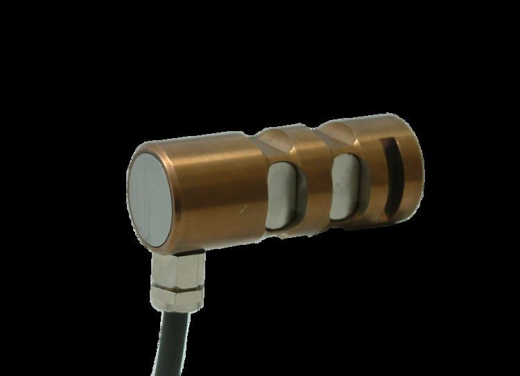
A Load pin is a proven design element that has been used for more than 50 years in metrology. In older books it is also known as Vibrometer.
Contents
Today's designations are:
Mounting
A force load pin must be attached in order to secure its alignment. Axial displacement must be secured first and rotation second. Proper securing is essential for obtaining accurate results. An axle holder pursuant to DIN15058 is used for this as standard.
Axle holder grooves are designed pursuant to DIN15058 in most cases. This standard recommends using one axle holder for diameters of up to 100mm and two axle holders per force loadpin for larger diameters. For best results, leave a small gap between the axle holder and the axle holder groove. This will allow the loadpin to bend freely in the outer support. Gap B should be approximately 0.2 mm.
Measurement principles
There are basically two methods of measurement principles in load pin. The first and most popular principle is with strain gauges. The second is based on measurement of magnetic field.
For a resistor based measurement Wheatstone bridge is used out of:
In magnetic measuring a transformer circuit is built. As an iron core the hole load pin is used. Through the strain of the load pin the magnetic properties of the material changes and thus the voltage at the secondary coil.