
 | ||
Mechanical railway signalling installations rely on lever frames for their operation to interlock the signals and points to allow the safe operation of trains in the area the signals control. Located in the signal box, the levers are operated by the signalman.
Contents
The world's biggest signal box is Severn Bridge Junction at Shrewsbury it has 180 levers making it the biggest, in not only the UK, but the World.
Overview
By the movement of individual levers, signals, points, level crossing gates or barriers and sometimes movable bridges over waterways are operated via wires and rods. The signaller chooses the correct combination of points, facing point locks and signals to operate, which will control the movement of each train through his or her area of control.
The lever frame contains interlocking designed to ensure that the levers cannot be operated to create a conflicting train movement. Each interlocking installation is individual and unique to the location controlled. The interlocking may be achieved mechanically or by electric lever locks, or (more usually) a combination of both.
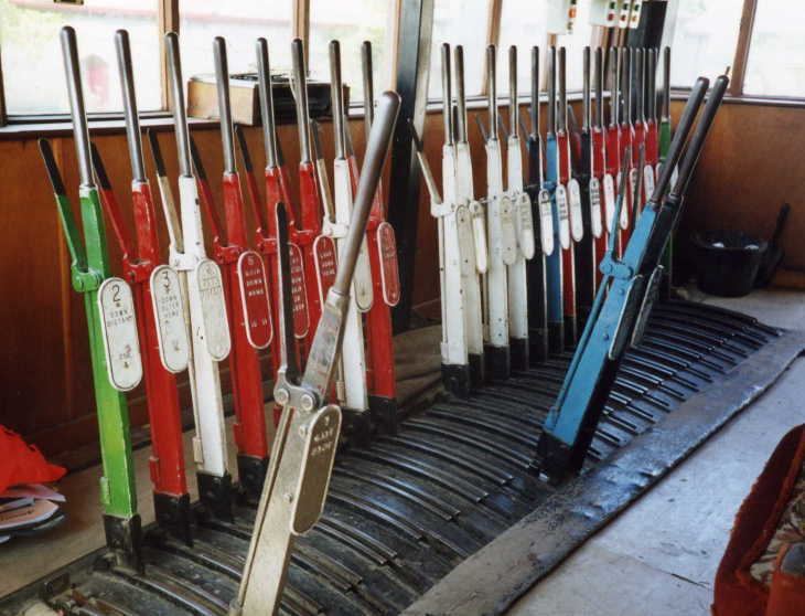
Signals or points located some distance away from the signal box are sometimes electrically rather than mechanically operated. Movement of the controlling lever operates an electrical circuit controller. In the UK, it is practice to cut short the handles of any levers controlling electrical apparatus, to remind signalmen that little effort is required to move them.
Mechanical lever frames and interlocking have now largely been replaced by modern, much larger electrical or electronic route interlockings located in Power Signal Boxes and more recently Integrated Electronic Control Centres which are able to control much larger areas of the rail network.
The world's largest lever frame (191 levers) is thought to be in the Spencer Street No.1 signal box in Melbourne, Australia.
Signallers are often seen using towels to cover the handles of the levers. This is to prevent sweat from the operator's hands transferring to the handle and corroding the metal.
Ground frames
A ground frame is a small lever frame located beside a railway, usually at ground level. A ground frame does not normally require any form of shelter since it is usually operated by traincrew and not permanently staffed. A ground frame is typically used to control the points giving access to an infrequently used siding or an emergency crossover, where the expense of providing control from a remote signal box cannot be justified. In some situations, signals may be worked from a ground frame.
In most cases, a ground frame has to be released from a signal box before it can be used. Typical methods of release include:
Once the ground frame has been released, the other levers controlling the points could be moved. When shunting was completed, the release cannot be restored until all levers are set back to their normal positions, allowing the main line to be used again. The train would then continue on its way.
If it was necessary for the train to be on the sidings controlled by the ground frame for a considerable time, it was desirable to release the running line so other trains could travel through the block section. To achieve this, a token instrument would be provided in a lineside hut near the ground frame. Once the train was off the main line, the points would be set back to normal, allowing the token to be removed from the ground frame. It would be then inserted into the token instrument in the hut, releasing the instruments at both ends of the section, so either signal box could then remove a token for another train to use the line, whilst the shunting train was in the sidings.
The modern equivalent of a ground frame, with switches instead of levers, is called a Ground Switch Panel (GSP). Points or signals worked from a ground switch panel are usually electrically operated.
Power frames
The lever frame principle of operation was perpetuated in the earliest power signalling installations. Since the signals and points worked electrically, no mechanical effort was needed to move the levers, which could therefore be miniaturised. In some cases, the interlocking was still done mechanically, but in others, electric lever locks were used.
Westinghouse Brake & Saxby Signal Co. Ltd. was one of the companies that produced miniature power lever frames. All-electric power lever frames were produced from 1929 onwards; earlier mechanical frames were produced before this date. In the UK, the Style 'L' all-electric miniature power lever frame was the most predominant on UK main line railways.
The Style 'B' & 'K' miniature power lever frames were the historical precursor frames in the development process of the Style 'L' frame.
London Underground railways used miniature power lever frames; initially Style 'B' was used. Later on, Style 'N' was introduced. This is a mechanically locked version of the Style 'L' frame. Style 'M', 'M2' and 'V' were also used.
Identification of lever functions
To assist the operator in determining their functions, each lever in a frame will generally be uniquely labelled, one common method being to number the levers in order from left to right. A lever's identification may be painted on its side or engraved on a badge or plate fitted either to the lever or behind it. This may be accompanied by a description of the lever's function. Usually, a large track diagram is positioned within easy view of the operator, which clearly shows each lever number adjacent to symbols representing the items of equipment that they operate. Levers are commonly coloured according to the type of equipment they control, the code of colours varying between different railway administrations. For example, in British practice, the following code generally applies: a red lever controls a stop signal or shunt signal, a yellow lever controls a distant signal, a black lever controls a set of points, a blue lever controls a facing point lock, and a white lever is spare. Brown levers are used to lock level crossing gates.
Manufacturers
In the UK, larger railway companies like the Great Western Railway (GWR) and the London and North Western Railway (LNWR) developed their own mechanical interlocking systems, whilst most smaller independent railway companies installed signalling products and systems bought from such firms as The Railway Signal Company (RSC) and The Westinghouse Brake and Signal Company (WB&SCo).