
 | ||
The Kelvin-Varley voltage divider, named after its inventors William Thomson, 1st Baron Kelvin and Cromwell Fleetwood Varley, is an electronic circuit used to divide voltages, i.e. to generate an output voltage as a precision ratio of an input voltage, with several decades of resolution. In effect, the Kelvin–Varley divider is an electromechanical precision digital-to-analog converter.
Contents
The circuit is used for precision voltage measurements in calibration and metrology laboratories. It can achieve resolution, accuracy and linearity of 0.1 ppm (1 in 10 million).
Circuit
The conventional voltage divider (Kelvin divider) uses a tapped string of resistors connected in series. The fundamental disadvantage of this architecture is that resolution of 1 part in 1000 would require 1000 precision resistors.
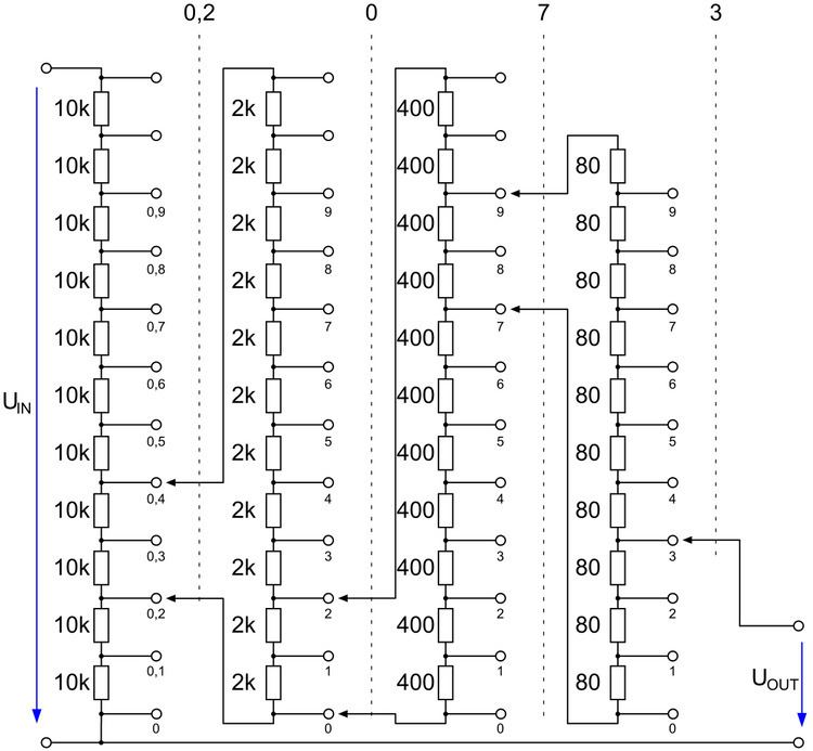
To overcome this limitation, the Kelvin–Varley divider uses an iterated scheme whereby cascaded stages consisting of eleven precision resistors provide one decade of resolution per stage. Cascading three stages, for example, therefore permits any division ratio from 0 to 1 in increments of 0.001 to be selected.
Each stage of a Kelvin–Varley divider consists of a tapped string of equal value resistors. Let the value of each resistor in the i-th stage be Ri Ω. For a decade stage, there will be eleven resistors. Two of those resistors will be bridged by the following stage, and the following stage is designed to have an input impedance of 2 Ri. That design choice makes the effective resistance of the bridged portion to be Ri. The resulting input impedance of the i-th stage will be 10 Ri.
In the simple Kelvin-Varley decade design, the resistance of each stage decreases by a factor of 5: Ri+1 = Ri / 5. The first stage might use 10 kΩ resistors, the second stage 2 kΩ, the third stage 400 Ω, the fourth stage 80 Ω, and the fifth stage 16 Ω.
Application
The full precision of the circuit can only be realized with no output current flowing, since the output's effective source resistance is variable. Kelvin–Varley dividers are therefore usually applied in conjunction with a null detector to compare their output voltage against a known voltage standard, e.g. a Weston cell (which must also be used without drawing current from it).
The final stage of a Kelvin–Varley divider is just a Kelvin divider. For a decade divider, there will be ten equal value resistors. Let the value of each resistor be Rn Ohms. The input impedance of the entire string will be 10 Rn. Alternatively, the last stage can be a two resistor bridge tap.
Trimming
For high precision, it is only necessary to ensure the resistors in any one decade have equal resistances, with the first decade requiring the highest precision of matching. The resistors have to be selected for tight tolerances, and may need to have their resistance values individually trimmed to be equal. This selection or trimming only requires comparing the resistances of two resistors in each trimming step, which is easily accomplished by using a Wheatstone bridge circuit and a sensitive null detector — a galvanometer in the 19th century, or an electronically amplified instrument today .
The ratio of resistances from one decade to the next is, surprisingly, not critical — by using Ri+1 resistances slightly higher than Ri / 5 and connecting a trimming resistor in parallel to the entire preceding decade in order to trim the effective resistance down to 2 × Ri+1. In the above example, the second stage might use 3 kΩ resistors instead of 2 kΩ; connecting a (trimmable) resistor of 60 kΩ in parallel with the second stage brings the total input resistance of the second stage down to the 20 kΩ required.