
 | ||
Knx standard
KNX is a standardized (EN 50090, ISO/IEC 14543), OSI-based network communications protocol for building automation. KNX is the successor to, and convergence of, three previous standards: the European Home Systems Protocol (EHS), BatiBUS, and the European Installation Bus (EIB or Instabus). The KNX standard is administered by the KNX Association.
Contents
- Knx standard
- KNX protocol
- KNX system components
- Logical Topology and Individual Address Space
- Wire transmission
- Configuration modes
- KNX Products
- References
KNX protocol
The standard is based on the communication stack of EIB but enlarged with the physical layers, configuration modes and application experience of BatiBUS and EHS.
KNX defines several physical communication media:
KNX is designed to be independent of any particular hardware platform. A KNX Device Network can be controlled by anything from an 8-bit microcontroller to a PC, according to the needs of a particular implementation. The most common form of installation is over Twisted pair medium.
KNX is approved as an open standard to:
KNX Association, as of 1 March 2014, had 339 members/manufacturers from 37 countries. Japan's Fujitsu General was enlisted as member number 300. The complete list can be found here at knx.org
The KNX Association has partnership agreements with more than 30,000 installer companies in 100 countries and more than 60 technical universities as well as over 150 training centres.
The access to the KNX specification used to be restricted, however as from January 2016 the access is free assuming you have a free account on the knx association website.
KNX system components
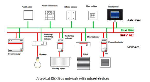
All the devices for a KNX installation are connected together by a two wire bus (the most common form of installation), thus allowing them to exchange data. The function of the individual bus devices is determined by their project planning, which can be changed and adapted at any time.
Sensors are the starting point for every action, because they gather information and send it on the bus as a data telegram. This can be information about room temperatures, movements, wind measurements or manually input instructions (Push buttons). Sensors are selected depending on the required application.
Actuators receive data telegrams which are then converted into actions. This can include controlling blinds, dimming lights or controlling heating and air conditioning systems. Actuators are also selected depending on the required application and consist of a bus coupler and an application module with the corresponding application program.
The application program is loaded into the devices together with the project design and commissioning software via a system component called interface (either serial or USB interface) connected to the PC and the bus. The two-wire installation bus is routed in parallel to the 230 V electrical power supply connects all devices and systems of the household technology together, and transmits all the control signals. It looks the same as the DALI protocol bus.
Logical Topology and Individual Address Space
KNX allows different bus topologies: tree, line and star topologies. These topologies can be mixed as needed. However, ring topologies are not allowed. The tree topology has advantages over other topologies in cases where a large network has to be created.
KNX is a fully distributed network, which accommodates up to 65,536 devices in a 16 bit Individual address space. The logical topology or sub network structure allows 256 devices on one line. As shown below, lines may be grouped together with a main line into an area. Up to 15 Lines can be connected to a main line via a line coupler (LC) for a total of 16 lines. The line couplers used to establish the lines from main line 1 have physical addresses from 1.1.0 to 1.15.0. 15 lines form an area. An entire domain is formed by 15 areas together with a backbone line using backbone/area couplers.
One line consists of a maximum of 4 line segments, each with a maximum of 64 bus devices. Each segment requires an appropriate power supply. Maximum segment length is 1000 m. 4 segments may be connected with line repeaters to establish a network length of 4000 m and 256 devices. The actual number of devices is dependent on the power supply selected and the power input of the individual devices. Note: Line repeaters may not be used on backbone or main lines. Note that KNX KNXnet/IP optionally allows the integration of KNX sub networks via IP. As shown above, this topology is reflected in the numerical structure of the individual addresses, which (with few exceptions) uniquely identify each node on the network. Note: Each line, including the main line, must have its own power supply unit. Installation restrictions may depend on implementation (medium, transceiver types, power supply capacity) and environmental (electromagnetic noise …) factors. Installation and product guidelines shall be taken into account.
Wire transmission
Twisted pair using differential signaling with a signaling speed of 9600 bit/s. Ideal wave resistance at 100 kHz is 120 Ω. Line resistance at 20 Ω/km, max 75 Ω/km. Maximum capacitance bus-to-bus line max 800 pF/m at 800 Hz. Higher capacitance requires proportionally shorter cable length. Bus power with 30 V DC and 25 mA Polarization critical. Devices within same physical segment are addressed with 8-bits Maximum 57600 network nodes. Media access control is controlled with the CSMA/CA method Maximum segment length is 1000 m. 4 segments may be connected with line repeaters to establish a network length of 4000 m. Loops are not allowed.
If the destination type flag (DT) is set the packet will be multicast or broadcast. R2-R0 is decremented for each routing hop, like TTL in IP. L3-L0 correspond to 1-16 user data bytes. Source is always a physical address. Destination may be either a physical or group address. Logical “0” is defined as impulse under the reference level 30 V DC. Logical “1” is lack of the same impulses.
There exist an alternative interface speed at 4800 bit/s taken over from BatiBUS. But KNX TP-0 products will only operate on the same network. But not be able to exchange information with BatiBUS devices.
Configuration modes
There are three categories of KNX device:
KNX Products
One of the strengths of the KNX system, is that any product labeled with the KNX trademark is not a mere declaration of the manufacturer but is based on conformity testing carried out by KNX accredited third party test labs. During these tests, it is not only checked that the device supports the KNX protocol but that its useful data is coded according to the KNX standardized Data types.
This results in devices of different manufacturers and different applications that can be combined to a working installation.
The KNX Association member companies have more than 7000 KNX certified product in their catalogues. This wide range of products allow, for example, the integration of:
On top of that you can enable access to the system via LAN, analog or mobile phone networks for having a central or distributed control of the system via PCs, Touch screens and Smartphones.