
 | ||
The J-pole antenna, more properly known as the J antenna, was first invented by Hans Beggerow in 1909 for use in Zeppelin airships. Trailed behind the airship, it consisted of a single element, one half wavelength long radiator with a quarter wave parallel feedline tuning stub. This concept evolved to the J configuration by 1936 attaining the name J Antenna by 1943.
Contents
Characteristics
The J-pole antenna is an end-fed omnidirectional half-wave antenna that is matched to the feedline by a quarter wave parallel transmission line stub of Lecher system form. Matching to the feed-line is achieved by sliding the connection of the feedline back and forth along the stub until an impedance match is obtained. Being a half-wave antenna, it provides a small gain over a quarter-wave ground-plane antenna.
Gain and radiation pattern
Primarily a dipole, the J-pole antenna exhibits a mostly circular pattern in the H plane with an average free-space gain near 2.2 dBi (0.1 dBd). Measurements and simulation confirm the quarter-wave stub modifies the circular H-plane pattern shape increasing the gain slightly on the side of the J stub element and reducing the gain slightly on the side opposite the J stub element. At right angles to the J-stub, the gain is closer to the overall average: about 2.2 dBi (0.1 dBd). The slight increase over a dipole's 2.15 dBi (0 dBd) gain represents the small contribution to the pattern made by the current imbalance on the matching section. The pattern in the E plane reveals a slight elevation of the pattern in the direction of the J element while the pattern opposite the J element is mostly broadside. The net effect of the perturbation caused by quarter-wave stub is an H-plane approximate gain from 1.5 to 2.6 dBi (-0.6 dBd to 0.5 dBd).
Environment
Like all antennas, the J-pole is sensitive to electrically conductive objects in its induction fields (aka reactive near-field region ) and should maintain sufficient separation to minimize these near field interactions as part of typical system installation considerations. The quarter wave parallel transmission line stub has an external electromagnetic field with strength and size proportional to the spacing between the parallel conductors. The parallel conductors must be kept free of moisture, snow, ice and should be kept away from other conductors including downspouts, metal window frames, flashing, etc. by a distance of two to three times the spacing between the parallel stub conductors. The J-Pole is very sensitive to conductive support structures and will achieve best performance with no electrical bonding between antenna conductors and the mounting structure.
Construction
Typical construction materials include metal tubing, ladder line, or twin-lead.
Feed
The J-pole antenna and its variations may be fed with balanced line. A coax feed line may be used if it includes a means to suppress feed-line RF currents. A folded-balun, sleeve balun or common-mode choke will suppress feed-line RF currents. The feed-point of the J-pole is somewhere between the closed low-impedance bottom and open high-impedance top of the J stub. Between these two extremes a match to any impedance between the low to high impedance points is available.
Mounting
The J-pole design functions well when fed with a balanced feed (via balun, transformer or choke) and no electrical connection exists between its conductors and surrounding supports. Historical documentation of the J antenna suggests the lower end of the matching stub is at zero potential with respect to earth and can connect to a grounding wire or mast with no effect on the antenna's operation. Later research confirms the tendency of the mast or grounding wire to draw current from the antenna potentially spoiling the antenna pattern. A common approach extends the conductor below the bottom of the J-pole resulting in additional and undesirable RF currents flowing over every part of the mounting structure. This modifies the far field antenna pattern typically, but not always, raising the primary lobes above the horizon reducing antenna effectiveness for terrestrial service. J-pole antennas with electrical connection to their supports often fare no better, and often much worse, than the simpler Monopole antenna. A mast decoupling stub reduces mast currents.
Slim Jim antenna
A variation of the J-pole is the Slim Jim antenna, also known as 2BCX Slim Jim, that is related to the J-pole the way a folded dipole is related to a dipole. The Slim Jim is one of many ways to form a J-Pole. Invented by Fred Judd (G2BCX), the name was derived from its slim construction and the J type matching stub (J Integrated Matching).
The Slim Jim variation of the J-pole antenna has characteristics and performance similar to a simple or folded Half-wave antenna and identical to the traditional J-pole construction. Judd found the Slim Jim produces a lower takeoff angle and better electrical performance than a 5/8 wavelength ground plane antenna. Slim Jim antennas made from ladder transmission line use the existing parallel conductor for the folded dipole element. In the copper pipe variation, the Slim Jim uses more materials for no performance benefit. Slim Jim antennas have no performance advantage over the traditional J-pole antenna.
The approximate gain in the H-plane of the Slim Jim is from 1.5 to 2.6 dBi (-0.6 dBd to 0.5 dBd).
Super-J antenna
The Super-J variation of the J-pole antenna adds an additional collinear half-wave radiator above the traditional J and connects the two with a phase stub to ensure both vertical half-wave sections radiate in current phase. The phasing stub between the two half-wave sections is often of the Franklin style.
The Super-J antenna compresses the vertical beamwidth and has more gain than the traditional J-pole design. Both radiating sections have insufficient separation to realize the maximum benefits of collinear arrays resulting in slightly less than the optimal 3 dB over a traditional J-pole or halfwave antenna.
The approximate gain in the H-plane of the Super-J antenna is from 4.6 to 5.2 dBi (2.4 dBd to 3.1 dBd).
Collinear J antenna
The collinear J antenna improves the Super-J by separating the two radiating half-wave sections to optimize gain using a phasing coil. The resulting gain is closer to the optimum 3 dB over a traditional J-pole or halfwave antenna.
The approximate gain in the H-plane of the Collinear J antenna is from 4.6 to 5.2 dBi (2.4 dBd to 3.1 dBd).
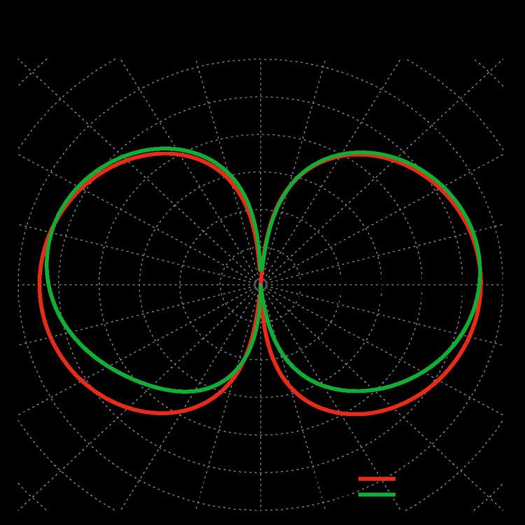
E-plane gain patterns of the variations
The graph compares the E-plane gain of the above three variations to the traditional J antenna.
The traditional J antenna and SlimJIM variation are nearly identical in gain and pattern. The Super-J reveals the benefit of properly phasing and orienting a second radiator above the first. The Collinear J shows slightly higher performance over the Super-J.