
 | ||
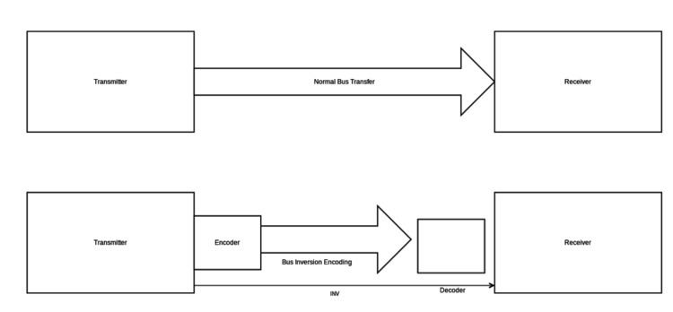
Inversion Encoding is an encoding technique used for encoding bus transmissions for low power systems. It is based on the fact that a large amount of power is wasted because of transitions, and thus reducing the transitions will help in power optimizations. This is done introducing an additional line named INV to the bus lines. This line determines whether the lines should be inverted or not.
Contents
Overview
The Bus-Invert encoding technique uses an extra signal (INV) to indicate the “polarity” of the data. Suppose we have an bus-invert code word INV@x where @ is the concatenation operator, and x denotes either the source word or its ones' complement. The bus-invert decoder takes the code word and produces the corresponding source word. If the INV signal is 1, the result is one’s complement of x, otherwise it is x.
Usage Situations
Bus-Invert method
- Compute the Hamming Distance (the number of bits in which they differ) between the present bus value (also counting the present invert line) and the next data value.
- If the Hamming distance is larger than n/2, set invert = 1, and make the next bus value equal to the inverted next data value.
- Otherwise let invert = 0, and let the next bus value equal to the next data value.
- At the receiver side the contents of the bus must be conditionally inverted according to the invert line, unless the data is not stored encoded as it is (e.g., in a RAM). In any case, the value of invert must be transmitted over the bus (the method increases the number of lines from n to n+1).
Example
Let us consider an example of a system which gets one of its data from a sensor. Most of the time, the sensor may be measuring some noise. For this example, let us consider that the values being measured are (0) and (-1) alternatively. For a 32-bit data bus, value 0 translates to 0x00000000 (0000 0000 0000 0000 0000 0000 0000 0000) while (-1) translates to 0xFFFFFFFF (1111 1111 1111 1111 1111 1111 1111 1111) in a 2’s complement representation. The Hamming distance in this case is 32 (since all 32-bits are changing their state). The Hamming distance is much smaller using the sign bit representation. However, even using 2’s complement, inversion encoding reduces the activity necessary. In this case 0 would be represented as 0x00000000 with INV=0 and -1 would be represented as 0x00000000 with INV=1. Since INV=1, the receiver would invert the data before consuming it, thereby converting it to 0xFFFFFFFF internally. In this case, only 1 bit (INV bit) is changed in the bus, leading to an activity of factor 1, which is even better than sign bit representation.
Performance Analysis
The bus-invert method generates a code that has the property that the maximum number of transitions per time-slot is reduced from n to n/2 and thus the peak power dissipation for input/output (I/O) is reduced by half. From the coding theory point of view, the bus-invert code is a time-dependent Markovian code.
While the maximum number of transitions is reduced by half, the average number has a smaller decrease. For an 8-bit bus for example, the average number of transitions, using bus-invert coding becomes 3.27 (instead of 4), or 0.41 (instead of 0.5) transitions per bus-line per time-slot. This means that the average number of transitions is 81.8% of the number with an unencoded bus. This is because the invert line contributes some transitions and the distribution of the Hamming distances is not uniform.
Partitioned Inversion Encoding
In order to decrease the average I/O power dissipation for wide buses the observation that the bus-invert method performs better for small bus sizes can be used to partition the bus into several narrower subbuses. Each of these subbuses can then be coded independently with its own invert signal. For example a 64-bit bus could be partitioned into eight 8-bit subbuses with a total of 8 added invert signals. Because of the assumption that the data to be transferred over the wide bus is uniformly distributed, the statistics for the narrower subbuses will be independent and the sequence of data for each subbus will be uniformly distributed. For example for a 64-bit bus partitioned into eight 8-bit subbuses the average number of transitions per time-slot will be 26.16 (8 times 3.27, the average for one 8-bit subbus) and the average number of transitions per bus-line per time-slot will be .41 (as for an 8-bit bus with one invert line). The maximum number of transitions is not improved by partitioning the bus and remains the same at n/2. However, there is always an extra overhead of using more lines, but computationally, it has been found that the inversion bus encoding works well for most purposes.