
 | ||
A hydraulic jump is a phenomenon in the science of hydraulics which is frequently observed in open channel flow such as rivers and spillways. When liquid at high velocity discharges into a zone of lower velocity, a rather abrupt rise occurs in the liquid surface. The rapidly flowing liquid is abruptly slowed and increases in height, converting some of the flow's initial kinetic energy into an increase in potential energy, with some energy irreversibly lost through turbulence to heat. In an open channel flow, this manifests as the fast flow rapidly slowing and piling up on top of itself similar to how a shockwave forms.
Contents
- Classes of hydraulic jumps
- Moving hydraulic jump
- Stationary hydraulic jump
- Analysis of the hydraulic jump on a liquid surface
- Height of the jump
- Energy dissipation by a hydraulic jump
- Location of hydraulic jump in a streambed or an engineered structure
- Air entrainment in hydraulic jumps
- Tabular summary of the analytic conclusions
- Hydraulic jump variations
- Shallow fluid hydraulic jumps
- Hydraulic jumps in abyssal fan formation
- Atmospheric hydraulic jumps
- Industrial
- Recreational
- References
The phenomenon is dependent upon the initial fluid speed. If the initial speed of the fluid is below the critical speed, then no jump is possible. For initial flow speeds which are not significantly above the critical speed, the transition appears as an undulating wave. As the initial flow speed increases further, the transition becomes more abrupt, until at high enough speeds, the transition front will break and curl back upon itself. When this happens, the jump can be accompanied by violent turbulence, eddying, air entrainment, and surface undulations, or waves.
There are two main manifestations of hydraulic jumps and historically different terminology has been used for each. However, the mechanisms behind them are similar because they are simply variations of each other seen from different frames of reference, and so the physics and analysis techniques can be used for both types.
The different manifestations are:
A related case is a cascade – a wall or undulating wave of water moves downstream overtaking a shallower downstream flow of water as shown in Figure 5. If considered from a frame of reference which moves with the wave front, this is amenable to the same analysis as a stationary jump.
These phenomena are addressed in an extensive literature from a number of technical viewpoints.
Classes of hydraulic jumps
Hydraulic jumps can be seen in both a stationary form, which is known as a "hydraulic jump", and a dynamic or moving form, which is known as a positive surge or "hydraulic jump in translation". They can be described using the same analytic approaches and are simply variants of a single phenomenon.
Moving hydraulic jump
A tidal bore is a hydraulic jump which occurs when the incoming tide forms a wave (or waves) of water that travel up a river or narrow bay against the direction of the current. As is true for hydraulic jumps in general, bores take on various forms depending upon the difference in the waterlevel upstream and down, ranging from an undular wavefront to a shock-wave-like wall of water. Figure 3 shows a tidal bore with the characteristics common to shallow upstream water – a large elevation difference is observed. Figure 4 shows a tidal bore with the characteristics common to deep upstream water – a small elevation difference is observed and the wavefront undulates. In both cases the tidal wave moves at the speed characteristic of waves in water of the depth found immediately behind the wave front. A key feature of tidal bores and positive surges is the intense turbulent mixing induced by the passage of the bore front and by the following wave motion.
Another variation of the moving hydraulic jump is the cascade. In the cascade, a series of roll waves or undulating waves of water moves downstream overtaking a shallower downstream flow of water.
Stationary hydraulic jump
The stationary hydraulic jump is most frequently seen on rivers and on engineered features such as outfalls of dams and irrigation works. They occur when a flow of liquid at high velocity discharges into a zone of the river or engineered structure which can only sustain a lower velocity. When this occurs, the water slows in a rather abrupt rise (a step or standing wave) on the liquid surface.
Comparing the characteristics before and after, one finds:
The other stationary hydraulic jump occurs when a rapid flow encounters a submerged object which throws the water upwards. The mathematics behind this form is more complex and will need to take into account the shape of the object and the flow characteristics of the fluid around it.
Analysis of the hydraulic jump on a liquid surface
In spite of the apparent complexity of the flow transition, application of simple analytic tools to a two dimensional analysis is effective in providing analytic results which closely parallel both field and laboratory results. Analysis shows:
Height of the jump
The height of the jump is derived from the application of the equations of conservation of mass and momentum. There are several methods of predicting the height of a hydraulic jump.
They all reach common conclusions that:
For a known flow rate
In fluid dynamics, the equation of continuity is effectively an equation of conservation of mass. Considering any fixed closed surface within an incompressible moving fluid, the fluid flows into a given volume at some points and flows out at other points along the surface with no net change in mass within the space since the density is constant. In case of a rectangular channel, then the equality of mass flux upstream (
with
For a straight prismatic rectangular channel, the conservation of momentum flux across the jump, assuming constant density, can be expressed as:
In rectangular channel, such conservation equation can be further simplified to dimensionless M-y equation form, which is widely used in hydraulic jump analysis in open channel flow.
Jump height in terms of flow Dividing by constant
which, after some algebra, simplifies to:
where
Negative answers do not yield meaningful physical solutions, so this reduces to:
known as Bélanger equation. The result may be extended to an irregular cross-section.
This produces three solution classes:
This is equivalent to the condition that
Practically this means that water accelerated by large drops can create stronger standing waves (undular bores) in the form of hydraulic jumps as it decelerates at the base of the drop. Such standing waves, when found downstream of a weir or natural rock ledge, can form an extremely dangerous "keeper" with a water wall that "keeps" floating objects (e.g., logs, kayaks, or kayakers) recirculating in the standing wave for extended periods.
Energy dissipation by a hydraulic jump
One of the most important engineering applications of the hydraulic jump is to dissipate energy in channels, dam spillways, and similar structures so that the excess kinetic energy does not damage these structures. The rate of energy dissipation or head loss across a hydraulic jump is a function of the hydraulic jump inflow Froude number and the height of the jump.
The mathematical formula for Energy loss in hydraulic jump is as follows:
Location of hydraulic jump in a streambed or an engineered structure
In the design of a dam the energy of the fast-flowing stream over a spillway must be partially dissipated to prevent erosion of the streambed downstream of the spillway, which could ultimately lead to failure of the dam. This can be done by arranging for the formation of a hydraulic jump to dissipate energy. To limit damage, this hydraulic jump normally occurs on an apron engineered to withstand hydraulic forces and to prevent local cavitation and other phenomena which accelerate erosion.
In the design of a spillway and apron, the engineers select the point at which a hydraulic jump will occur. Obstructions or slope changes are routinely designed into the apron to force a jump at a specific location. Obstructions are unnecessary, as the slope change alone is normally sufficient. To trigger the hydraulic jump without obstacles, an apron is designed such that the flat slope of the apron retards the rapidly flowing water from the spillway. If the apron slope is insufficient to maintain the original high velocity, a jump will occur.
Two methods of designing an induced jump are common:
In both cases, the final depth of the water is determined by the downstream characteristics. The jump will occur if and only if the level of inflowing (supercritical) water level (
Air entrainment in hydraulic jumps
The hydraulic jump is characterised by a highly turbulent flow. Macro-scale vortices develop in the jump roller and interact with the free surface leading to air bubble entrainment, splashes and droplets formation in the two-phase flow region. The air–water flow is associated with turbulence, which can also lead to sediment transport. The turbulence may be strongly affected by the bubble dynamics. Physically, the mechanisms involved in these processes are complex.
The air entrainment occurs in the form of air bubbles and air packets entrapped at the impingement of the upstream jet flow with the roller. The air packets are broken up in very small air bubbles as they are entrained in the shear region, characterised by large air contents and maximum bubble count rates. Once the entrained bubbles are advected into regions of lesser shear, bubble collisions and coalescence lead to larger air entities that are driven towards the free-surface by a combination of buoyancy and turbulent advection.
Tabular summary of the analytic conclusions
NB: the above classification is very rough. Undular hydraulic jumps have been observed with inflow/prejump Froude numbers up to 3.5 to 4.
Hydraulic jump variations
A number of variations are amenable to similar analysis:
Shallow fluid hydraulic jumps
Figure 2 above illustrates a daily example of a hydraulic jump can be seen in the sink. Around the place where the tap water hits the sink, you will see a smooth-looking flow pattern. A little further away, you will see a sudden "jump" in the water level. This is a hydraulic jump.
The nature of this jump differs from those previously discussed in the following ways:
Changes in the behavior of the jump can be observed by changing the flow rate.
Hydraulic jumps in abyssal fan formation
Turbidity currents can result in internal hydraulic jumps (i.e., hydraulic jumps as internal waves in fluids of different density) in abyssal fan formation. The internal hydraulic jumps have been associated with salinity or temperature induced stratification as well as with density differences due to suspended materials. When the slope of the bed (over which the turbidity current flows) flattens, the slower rate of flow is mirrored by increased sediment deposition below the flow, producing a gradual backward slope. Where a hydraulic jump occurs, the signature is an abrupt backward slope, corresponding to the rapid reduction in the flow rate at the point of the jump.
Atmospheric hydraulic jumps
A related situation is the Morning Glory cloud observed, for example, in Northern Australia, sometimes called an undular jump.
Industrial
The hydraulic jump is the most commonly used choice of design engineers for energy dissipation below spillways and outlets. A properly designed hydraulic jump can provide for 60-70% energy dissipation of the energy in the basin itself, limiting the damage to structures and the streambed. Even with such efficient energy dissipation, stilling basins must be carefully designed to avoid serious damage due to uplift, vibration, cavitation, and abrasion. An extensive literature has been developed for this type of engineering.
Recreational
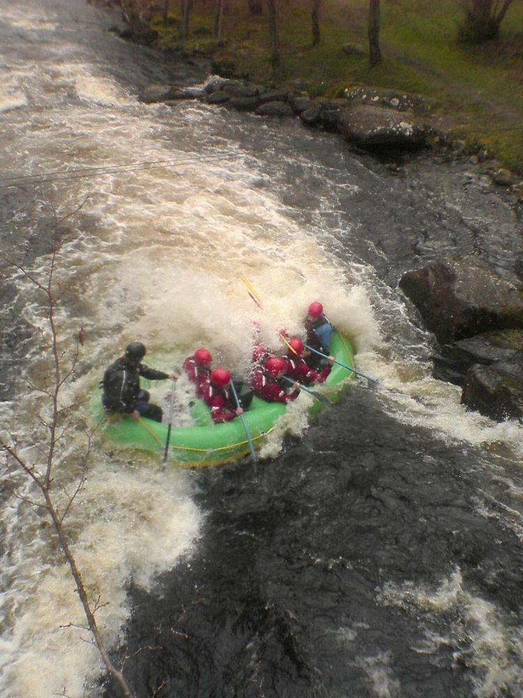
While travelling down river, kayaking and canoeing paddlers will often stop and playboat in standing waves and hydraulic jumps. The standing waves and shock fronts of hydraulic jumps make for popular locations for such recreation.
Similarly, kayakers and surfers have been known to ride tidal bores up rivers.