
 | ||
Hybrid masonry is a new type of building system that uses engineered, reinforced masonry to brace frame structures. Typically, hybrid masonry is implemented with concrete masonry panels used to brace steel frame structures. The basic concept is to attach a reinforced concrete masonry panel to a structural steel frame such that some combination of gravity forces, story shears and overturning moments can be transferred to the masonry. The structural engineer can choose from three different types of hybrid masonry (I, II, or III) and two different reinforcement anchorage types (a & b). In conventional steel frame building systems, the vertical force resisting steel frame system is supported in the lateral direction by steel bracing or an equivalent system. When the architectural plans call for concrete masonry walls to be placed within the frame, extra labor is required to ensure the masonry fits around the steel frame. Usually, this placement does not take advantage of the structural properties of the masonry panels. In hybrid masonry, the masonry panels take the place of conventional steel bracing, utilizing the structural properties of reinforced concrete masonry walls.
Contents
The system was first introduced by David Biggs, PE in 2007 at the 10th North American Masonry Conference and was based on historical masonry construction and the practice of anchoring masonry walls in steel frames for out of plane strength.
Types
There are five different configurations of hybrid masonry. They consist of three different main types with two subsets; however, the first type does not allow both subsets. The three types consist of different constraint conditions within the steel frame and the two subsets are based on the anchoring of the vertical reinforcement in the masonry panel.
Type I
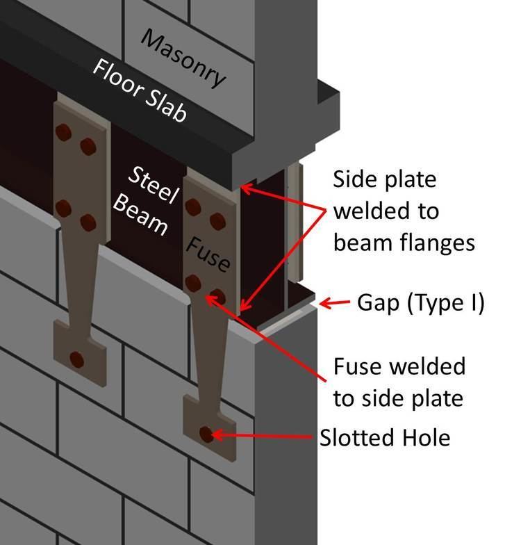
Type I hybrid masonry has no direct contact with the surround steel frame. For this reason, there are not two subsets of this configuration. Lateral forces are transmitted to the masonry panel through steel plates that are connected to the floor beams and attached to the wall with a through-bolt. The hole in the plate for the through-bolt is slotted so that gravity loads are not transmitted to the masonry panel; the vertical loads travel solely through the steel frame. Thus, the masonry panel takes only the story shear from the above floors and acts as a one story shear wall.
The steel plates can be designed in two manners. If the design engineer wishes the steel plate to be the weak point, the plate can be designed as a fuse. The fuse would dissipate energy after yielding and be easily replaced after an extreme event. Alternatively, the plate can be designed so it does not yield before the masonry panel experiences significant damage. A strong plate would localize the damage to the masonry.
Type II
Type II hybrid masonry is constrained vertically by the steel frame; however, the sides of the panel still have a gap between the steel and the masonry. The vertical contact transfers the gravity load from the beam into the masonry panel, increasing its flexural and shear strength. Instead of the plates transferring the lateral force from the steel to the masonry, shear studs are welded to the bottom side of the beam. Grout is then used to fill the space between the masonry and the steel beam. With this contact, the wall is subject to story shears, gravity loads, as well as overturning moments much like a continuous shear wall.
The two subsets of Type II hybrid masonry are Type IIa and Type IIb. The difference between the two systems are whether the vertical reinforcement is anchored into the base or to the steel beam. In Type IIa, the vertical reinforcement is anchored and can develop tension forces along its length. The vertical reinforcement is not anchored in Type IIb hybrid masonry and consequently the rebar cannot take the force on the tension side of the wall. Instead, the top of the wall undergoes compression.
Type III
Similar Type II hybrid masonry, Type III hybrid masonry has the vertical confinement. In addition to the vertical contact with the beam, contact with the columns is also used for horizontal confinement. Shear studs are welded on the insides of the columns to transfer vertical forces that are the result of axial load in the columns as well as shear in the wall. The wall system resembles infill masonry in terms of confinement in the steel, yet differs in that it is grouted and reinforced, allowing for a more ductile response.
Research
Prof. Ian Robertson at the University of Hawaiʻi -Mānoa(UHM) has developed and tested the steel plate connections between the masonry. The result was a design method of a fuse plate that yields along its entire length, with the aim of creating a ductile energy dissipating fuse. Bolt pullout tests were also performed at UHM to validate the strength of the masonry with through bolts. A research team at Rice University develops computational models for the study of hybrid masonry structural systems. Profs. Larry A. Fahnestock and Daniel P. Abrams are performing full scale experimental tests on hybrid masonry at the Network for Earthquake Engineering Simulation(NEES) site at the University of Illinois at Urbana-Champaign.