
Country England Construction began 1955 | Status Decommissioned Nameplate capacity 1000 MW Decommission date 2003 | |
 | ||
Operators | ||
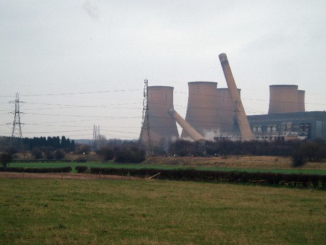
Goodbye high marnham power station demolition
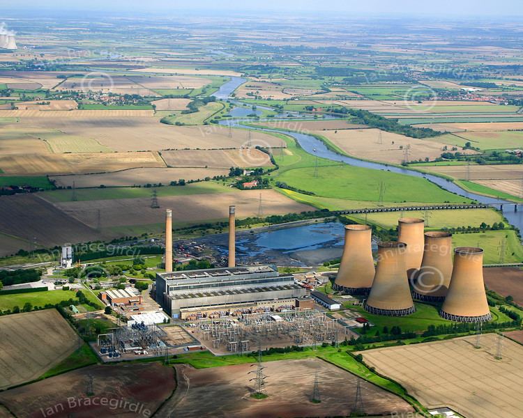
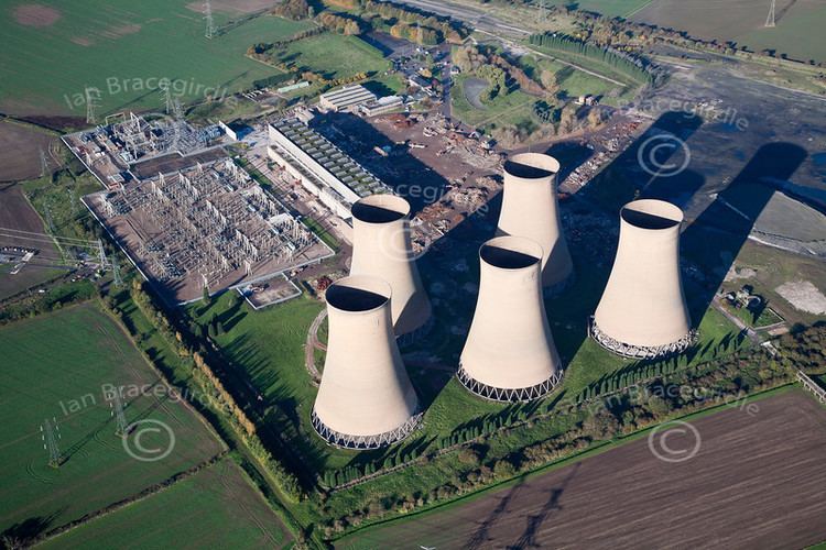
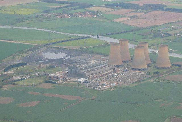
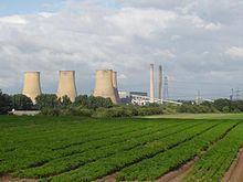
High Marnham Power Station was a coal-fired power station. It was located in Nottinghamshire, to the west of the River Trent, approximately 0.5 miles (0.8 km) north of the village of Marnham.
Contents
- Goodbye high marnham power station demolition
- High marnham power station r i p
- Boiler plantEdit
- Boiler water feed systemEdit
- Turbinegenerator plantEdit
- Cooling water plantEdit
- Coal plantEdit
- Closure and demolitionEdit
- References
High Marnham was the most southerly of three power stations which lined the River Trent, known locally as Megawatt Valley, the others being West Burton and Cottam. The station was constructed by the CEGB Northern Project Group, overseen by resident engineer Douglas Derbyshire and the main contractor Alfred McAlpine. The power station was constructed on a "green field" site, started in November 1955 and fully commissioned by 1962. It was the first 1000 MW [946 MW net] power station built and commissioned in Europe, and operated at higher boiler pressure and temperature values than previously commissioned.
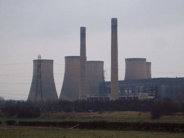
High marnham power station r i p
Boiler plantEdit
Designed and built by International Combustion Ltd., four boiler units, each weighing about 14,000 tons, were suspended on beams and support columns for a vertical expansion of 8 inches (200 mm). Each boiler was built in twin furnace construction with 1.5 inches (38 mm) bore tubes, all connected to a common drum at the top of the boiler, and fitted with safety valves set at 2,500 pounds per square inch (17,000 kPa). One furnace carried the superheat pendants, connected to the boiler drum top and to an outlet header, fitted with a safety valve set at 2,450 pounds per square inch (16,900 kPa). The second furnace carried the reheat pendants connected to an inlet header from the HP cylinder exhaust and to an outlet header to the turbine IP cylinder. The lower section of the furnace corners contained a wind box with the pulverised fuel nozzles and retractable oil burners. Fuel nozzles and burners were aligned at an imaginary circle in the furnace ensuring an even heat distribution. Pulverised fuel nozzles were provided with vertical movement to control temperature conditions. At the bottom of each furnace, the front and rear wall tubes were formed into an inward slope where the tubes were bent back (forming a nose and gap) to their original vertical wall alignment terminating at their front and rear bottom furnace water tube headers. A steel skirt was fitted around each furnace base. [see ash hoppers]
Water circulation within the boiler furnace was assisted by fully immersed electrical pumps manufactured by Hayward Tyler Co. The pulverised fuel plant was built and installed by International Combustion Ltd. Four Lopulco coal roller mills with pulverised coal fans per boiler were located in the boiler house basement. Coal was fed from overhead bunkers by speed-regulated drum feeders to the mills and crushed to fine dust by three 7.5 ton roller doors per mill, then blown into the wind boxes through pipework and the PF nozzles. Combustion air was delivered by two forced draught fans located above the coal bunkers, taking warm air from above the boiler roof casing and discharging it though rotating heat exchangers to the furnace wind boxes. Hot gas was drawn from the furnaces through the pendants, water tube economisers, rotating heat exchanger, cyclone dust collectors and electrostatic precipitators by two induced draught fans before entering the chimney flue ducts and passing up the 500 feet (150 m) high chimneys.
Heavy combustion products fell into basement mounted hoppers with water troughs under each furnace that engaged with the bottom furnace header casing skirt. The hoppers were emptied by a water jet/sluice arrangement into an ash receiving pit.
Boiler water feed systemEdit
Condensed steam was taken from the turbine condenser and pumped back into the boiler feed system, via the unit evaporator, low and high pressure water tube heaters (after being subjected to bled steam heat from turbine cylinders) into a de-aerator. The de-aerated water was taken by the main feed pump (multi stage cartridge design pump or a smaller start up pump) and discharged at 3,000 pounds per square inch (21,000 kPa) into the boiler water feed system through feed regulating valves. Both feed pump types were electric motor driven. Additional station boiler feed water supply could also be made up by the station water treatment plant and fed into the de-aerator, this was operated and controlled by the station chemistry department.
Turbine/generator plantEdit
Designed and built by the English Electric Co., four steam turbine units of high pressure, intermediate pressure and double-flow low pressure turbine cylinders were coupled to 250 MW generators. The steam flow into the turbine was regulated by the hydraulically controlled steam inlet valves to maintain a generating speed of 3000 RPM. The turbine over-speed protection was by weight eccentric rings on the turbine shaft, set to throw-out at a predetermined RPM and shutting the HP cylinder inlet steam valves. Exhaust flow from the HP turbine cylinders passed to the boiler for reheating (with some having been bled off to feed heaters), returned to the IP cylinder (with some bled off to LP feed heaters) and exhausted from the double-flow LP cylinder under vacuum into underslung water-cooled condensers. Condenser cooling water was delivered from a sub-basement ring main around the turbine house. The turbine/generator assembly was mounted on reinforced concrete pedestals that ran along the length of the turbine hall.
Cooling water plantEdit
Cooling water pumps were located between cooling towers in a purpose made building to deliver cooling water into a ring main for the turbine condensers. The warm water was passed on through to the 350 feet (110 m) cooling towers, falling into the tower moats to be channelled back through screens and a chlorination process to the pump suctions for recirculation. Water loss through evaporation was made up from the river Trent by suction screened pumps.
Coal plantEdit
Located to the north of the main plant with a 10-mile spur from the mainline cross-country rail system, were a control room, coal wagon marshalling yard and conveyor systems. In about 1965 a "merry-go-round" system of automatic coal wagon unloading was installed to evaluate for future "Stations Systems". Bunker coal supply ran from the coal plant on inclined conveyors to the boiler house, where it was fed onto a moving "feed head" conveyor above the individual boiler coal bunkers.
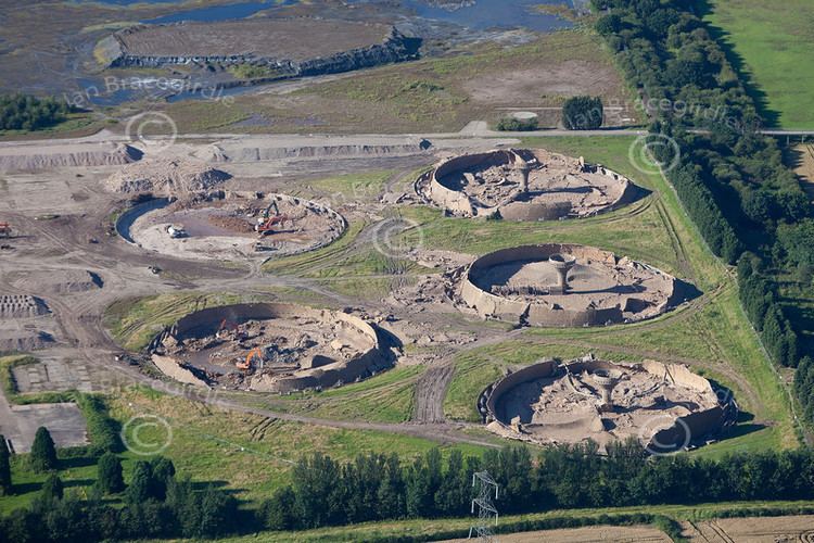
Closure and demolitionEdit
The station closed in 2003 after nearly 45 years in operation, with a loss of 119 jobs. The station's chimneys were demolished on 15 December 2004. The station's 150 feet (46 m)-high boiler house was demolished on 5 October 2006. The station's five cooling towers were demolished on 15 July 2012 at 10:00.
In late 2009, the railway connection that used to supply coal to the power station became Network Rail's High Marnham Test Track for innovation and development, suited to this purpose because the line is all-welded joints and laid on concrete sleepers.