
 | ||
The HRS type antenna is an example of a curtain array antenna. It has Horizontal dipoles with a Reflector behind them, and the beam is Steerable. These antennas are also known as "HRRS" (for a Reversible Reflector), but the extra R is seldom used.
Contents
- Description
- Nomenclature
- Steering
- Azimuth beamwidth
- Vertical Launch Angle
- Transmission system optimization for geopolitics
- Cost issues
- Examples of HRS antennas
- Shortwave relay stations using only HRS antennas
- Active sites
- Decommissioned sites
- RADAR Systems using HR Type Antennas
- References
Curtain arrays were developed during the 1920s and 1930s when there was a lot of experimentation with long distance shortwave broadcasting. The underlying concept is to achieve gain over the simple dipole antenna, possibly by folding one or more dipoles into a smaller physical space, or to arrange multiple dipoles such that their radiation patterns reinforce each other, thus concentrating more signal into a given target area.
The first curtain array to achieve popularity was the Sterba curtain, patented by Ernest J. Sterba in 1929 and this was used by Bell Labs and others during the 1930s and 1940s. The Sterba curtain is however a narrowband design and is only steerable by mechanical means. However, as far back as the mid-1930s, Radio Netherlands was using a rotatable HRS antenna for global coverage. Since the 1950s the HRS design has become more or less the standard for long distance high power shortwave broadcasting (> 1000 km).
Description
An HRS type antenna is basically a rectangular array of conventional dipole antennas strung between supporting towers. In the simplest case, each dipole separated from the next by λ/2 vertically, and the centres of each dipole are spaced 1λ apart horizontally. Again, in the simplest case (for a broadside beam), all dipoles are driven in phase with each other and with equal power. Radiation is concentrated broadside to the curtain.
Behind the array of dipoles, typically about 0.3λ away there will be a 'reflector' consisting of many parallel wires in the same orientation as the dipoles. If this was not present, the curtain would radiate equally forward and backward.
Nomenclature
Since 1984 the CCIR have standardised the nomenclature for this family of curtain antennas as follows:
First symbol: Indicates the orientation of the dipoles in the array. Could be the letter "H" for horizontal or the letter "V" for vertical, however no vertical polarisation arrays of this kind have ever been built apparently.
Second symbol (if present): the single letter "R" indicates that there is a simple (passive) reflector on one side of the array. Alternatively the letters "RR" indicates that the array has some kind of "reversible reflector", i.e. can put its beam out at 0° or 180°. Very few of this type have ever been built - RCI Sackville may have 2 HRRS type antennas—perhaps the only ones in North America.
Third symbol (if present): "S" indicates that the array is steerable (see below).
Following the letters come three numbers "x/y/z" where 'x' (an integer) is the number of dipoles counting horizontally. 'y' (an integer) is the number of dipoles counting vertically and 'z' (a decimal fraction) is the height above ground (in wavelengths) of the lowest row of dipoles in the array.
So, a "HRS 4/5/0.5" antenna curtain is 4 dipoles wide, and 5 dipoles high with the lowest row being 0.5 wavelengths off the ground and with a standard reflector. An HRS 4/4/0.5 is one of the standard types of array seen at shortwave broadcast stations worldwide.
Steering
If there is an "S" in the antenna's designation, then it is steerable. This might be achieved electronically by adjustment of the phases of the signals fed to the columns of dipoles, or physically by mounting the entire array on a gigantic rotator. An example of this can be seen at NRK Kvitsøy, where a short circular railway carries a pair of wheeled platforms at opposite ends of a diameter-arm. Each platform has one of the support towers for the curtain array standing on it, the curtain is slung between the towers.
Another physical rotation technique is employed by the ALLISS system where the entire array is built around a central rotatable tower of massive strength.
Electrically steered arrays can usually be steered about ±30° from the antenna's physical orientation. Physically rotated arrays can obviously manage the full 360°. Electrical steering is typically done in the horizontal plane, with some adjustments being possible in the vertical plane.
Azimuth beamwidth
Vertical Launch Angle
The number of dipole rows and the height of the lowest element above ground determine the elevation angle and consequently the distance to the service area.
Note that it is possible for details of the antenna site to wreak havoc with the designers plans such that takeoff angle and matching may be adversely affected.
Transmission system optimization for geopolitics
Cost issues
Examples of HRS antennas
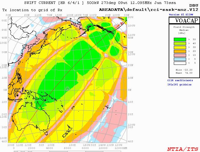
This is an example of theoretical HRS design shortwave relay stations. This may help one better understand HRS antenna directivity.
Shortwave relay stations using only HRS antennas
This is an incomplete list of stations using only HRS antennas, sorted by country name.
Active sites
Germany
New Zealand
UK
Decommissioned sites
Australia
Canada
Spain
USA
RADAR Systems using HR Type Antennas
Some portable tactical antenna systems still use HR type antennas, mostly not HRS as the antennas are rotatable.