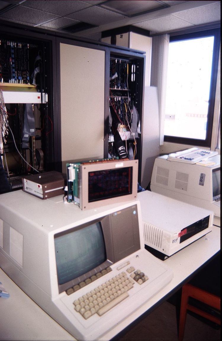
 | ||
The HP 64000, introduced circa 1980, is a tool for developing hardware and software for products based on commercial microcomputers. The earliest commercial 64000 development systems contain from one to six 64100A Development Stations sharing a hard drive and line printer. This arrangement allowed up to six designers and engineers to use their workstations together, sharing the HPIB instrumentation bus and a hard drive and a line printer. This was an innovative feature of the 64000 development system since other systems of the era used a timesharing system with a single system processor and memory, making for a more expensive and less flexible development system.
Contents
Description
The 64000 system is a complete emulation system consisting of a microprocessor emulator, a memory emulator, a logic analyzer, and a software package that interacts with the integrated hardware to form a complete development tool.
The three interfaces that comprise a 64000 system are as follows:
- the user interface as defined by the target processor's specifications.
- the high-speed emulation bus that connects the processor emulator, the memory emulator, and the logic analyzer.
- the 64100A mainframe bus is used to control the emulation processor and to communicate between the mainframe processor and the emulation processor.
Examine the functional diagram of the HP 64000 system to the right which illustrates the interaction between various system components.
Microprocessor emulator
The emulation systems available consists of two subsystems, 1) an external emulation pod which contains the target microprocessor and 2) an internal expansion card called the emulation control board which controls the microprocessor in the pod and interfaces it to the system timing and control signals of the 64100A workstation.
Emulator pods
These are pods external to the 64100A and 64110 mainframe. The pod is connected to a matching control board in the card cage by 2 sometimes 3 flat cables. It may also be connected to a target computer system's processors socket by a 40-pin plug for 8 bit processors or a 64-pin plugin for processors like the 68000 or 68010 64-pin dip socket.
The following is a list of available emulator pods for various target microprocessor systems.
Emulator control board
The control board which controls the interface to the pods is installed in the 64100A internal card cage. This emulator control board consists of:
The following table of available controller boards lists various target architectures for particular controllers. Given the generalized design features of the 64000 system, some controller boards are compatible with more than one microprocessor family.
Other expansion cards
The 64100A can support other expansion cards to aid in emulation or in prototyping.
