
 | ||
Developer(s) Image Analysis and Communications Laboratory Operating system Type Cardiac Motion Tracking Website HARP Overview (Software Download) | ||
Harmonic phase (HARP) algorithm is a medical image analysis technique capable of extracting and processing motion information from tagged magnetic resonance image (MRI) sequences. It was initially developed by N. F. Osman and J. L. Prince at the Image Analysis and Communications Laboratory at Johns Hopkins University. The method uses spectral peaks in the Fourier domain of tagged MRI, calculating the phase images of their inverse Fourier transforms, which are called harmonic phase (HARP) images. The motion of material points through time is then tracked, under the assumption that the HARP value of a fixed material point is time-invariant. The method is fast and accurate, and has been accepted as one of the most popular tagged MRI analysis methods in medical image processing.
Contents
Background
In cardiac magnetic resonance imaging, tagging techniques make it possible to capture and store the motion information of myocardium in vivo. MR tagging uses a special pulse sequence to create temporary features – tags in the myocardium. Tags deform together with the myocardium as the heart beats and are captured by MR imaging. Analysis of the motion of the tag features in many images taken from different orientations and at different times can be used to track material points in the myocardium. Tagged MRI is widely used to develop and refine models of normal and abnormal myocardial motion to better understand the correlation of coronary artery disease with myocardial motion abnormalities and the effects of treatment after myocardial infarction. However, suffered from long imaging and post-processing times, tagged MRI was slow in entering into routine clinical use until the HARP algorithm was developed and published in 1999.
HARP processing
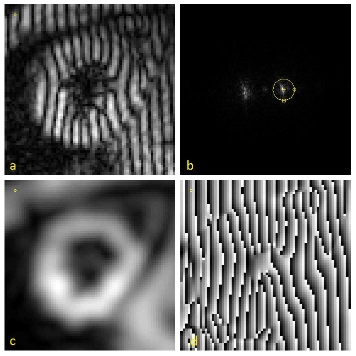
A tagged MRI showing motion of a human heart is shown in the image (a). The effect of tagging can be described as a multiplication of the underlying image by a sinusoid tag pattern having a certain fundamental frequency, causing an amplitude modulation of the underlying image and replicating its Fourier transform into the pattern shown in (b).
HARP processing uses a bandpass filter to isolate one of the spectral peaks. For example, the circle drawn in (b) is the -3 dB isocontour of the bandpass filter used to process this data. Selection of the filters for optimal performance is discussed in this paper. The inverse Fourier transform of the filtered image yields a complex harmonic image
where
Either
HARP tracking
For a fixed material point with a HARP value, only one of the points sharing the same HARP value in a later time frame is the correct match. If the apparent motion is small from one image to the next, it is likely that the nearest of these points is the correct point. The tracking result is very accurate in this case.
Consider a material point located at
The Newton-Raphson interative method is used to find a solution, which is:
In practice, since
The result of HARP tracking of one frame of cardiac MRI is shown in the figure. It is obtained by calculating both motions from horizontal direction and vertical direction, resulting in a 2D vector field showing the motion of every material point on the myocardium at this time frame.
The entire HARP algorithm takes only a few minutes to perform on a normal computer and the motion tracking result is accurate (with a typical error range of