
 | ||
Grade Crossing Signals are the electronic warning devices for road vehicles at railroad grade crossings.
Contents
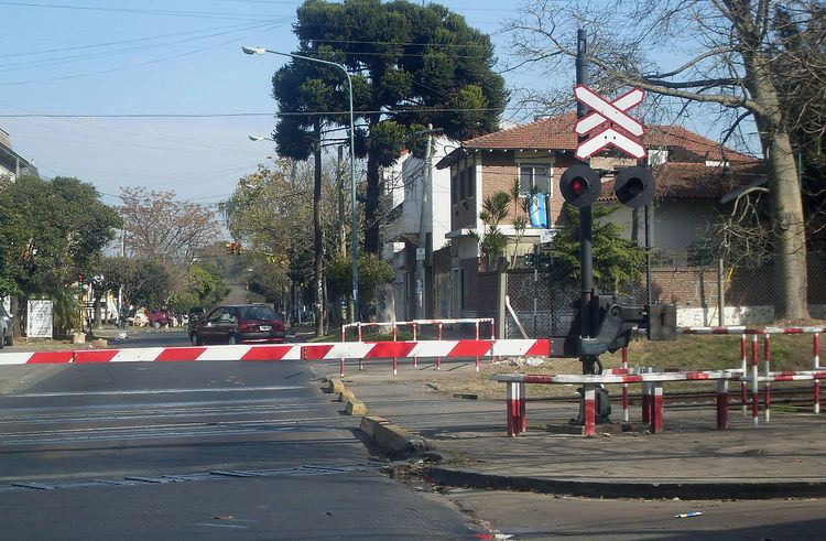
The basic signal consists of flashing red lights, a crossbuck and a bell, attached to a mast. At most crossings, the signals will activate about 30 seconds before the train arrives.
At crossings where trains travel at 30 miles per hour (48 km/h) or more, there will be a gate added to the signal. The gates will be fully lowered 15 to 20 seconds before the train arrives. The gates will rise or the signals will shut off once the end of the train clears the island circuit.
The time interval may be controlled by a grade crossing predictor, an electronic device which is connected to the rails of a railroad track, and activates the crossing's warning devices (lights, bells, gates, etc.) at a consistent interval prior to the arrival of a train at a grade crossing.
Crossbucks also may have legends saying, for example: "RAIL ROAD CROSSING" (United States), "RAIL WAY CROSSING" (Australia), "PELIGRO FERROCARRIL" (Latin America), or wordless (Canada).
Many states in the US are now requiring the use of this type of equipment at all newly constructed grade crossings.
First devices
"Wigwag" was the nickname given to a type of crossing signals once common in North America, named for the pendulum-like motion it used to signal the approach of a train. Albert Hunt, a mechanical engineer at Southern California's Pacific Electric (PE) interurban streetcar railroad, invented it in 1909 for safer railroad grade crossings.
In 1914, utilized alternating electromagnets pulling on an iron armature. A red steel target disc, slightly less than two feet in diameter, serving as a pendulum was attached. A red light in the center of the target illuminated, and with each swing of the target a mechanical gong sounded.
The new model, combining sight, motion and sound was dubbed the "Magnetic Flagman" and produced by the Magnetic Signal Company.
Modern devices
First developed in concept by the Stanford Research Institute in the late 1950s at the request of the Southern Pacific Company (the Southern Pacific Railroad, now merged into the Union Pacific Railroad), and patented in 1966, the design goal of the grade crossing predictor was to provide a consistent warning time for trains approaching a grade crossing.
Before this invention, the circuits used for activating a crossing's warning devices were very simple, activated whenever a train came within a fixed distance (hundreds or thousands of feet) of the crossing. This method required that the crossing be designed to accommodate a train approaching at the track speed limit, which leads to longer warning times for trains approaching the crossing at lower speeds. Very slow trains could have many minutes of warning time, thus delaying highway traffic unnecessarily.
Technology
All grade crossing predictors rely on the changes in the electrical characteristics of the rails that occur as a train approaches the point at which the predictor is connected to the rails (the feedpoint). A railroad track occupied by a train or other electrical shunt can be viewed as a single-turn inductor shaped like a hairpin. As the train approaches the feedpoint, the area enclosed by the inductor diminishes, thus reducing the inductance.
This inductance can be measured by connecting a constant-current alternating current source to the rails, and measuring the voltage which results. By Ohm's Law, the voltage measured will be proportional to the impedance. The absolute magnitude of this voltage and its rate of change can then be used to compute the amount of time remaining before the train arrives at the crossing, assuming it is running at a constant speed.
The crossing's warning devices are activated as soon as the computed time until the train reaches the crossing reaches some programmed threshold. The earliest grade crossing predictors used analog computers to perform this calculation, but modern equipment uses digital microprocessors.
Implementation
A predictor includes a short island track which just covers the width of the level crossing.
A predictor circuit in the middle of nowhere is usually terminated with a dead short across the rails at the outer ends. This assumes that there are no ordinary track circuits for block signalling purposes.
Two predictor circuits may overlap, with tuned circuits used for one predictor to jump over the other. The tuned loops would be a dead short for one predictor, and an open circuit for the other.