
 | ||
The Goldschmidt alternator or reflector alternator, invented in 1908 by German engineer Rudolph Goldschmidt, was a rotating machine which generated radio frequency alternating current and was used as a radio transmitter. Radio alternators like the Goldschmidt were some of the first continuous wave radio transmitters. Like the similar Alexanderson alternator, it was used briefly around World War I in a few high power longwave radio stations to transmit transoceanic radiotelegraphy traffic, until the 1920s when it was made obsolete by vacuum tube transmitters.
Contents
Description
Although the device was a radio transmitter, it resembled an electric generator used to produce electric power in a power plant. Like other generators it consisted of a rotor, several feet in diameter, wound with coils of wire, which rotated inside a stationary frame called a stator which had its own coils. The interaction between the magnetic fields of the rotor and stator produced radio frequency currents in the stator windings, which were applied to the antenna.
A radio frequency alternator differed from an ordinary electric generator in that to produce radio frequency current it rotated much faster, and had many more magnetic "poles" on the rotor and stator, usually 300 to 600. The Goldschmidt alternator was turned by a powerful DC electric motor attached to the shaft, through a geartrain which increased the motor's speed to several thousand RPM. The advantage of the Goldschmidt design was that by using external "reflector" capacitor banks that increased the frequency of the current to a multiple (harmonic) of the alternator's rotation speed, it allowed the rotation speed to be kept lower, simplifying the mechanical design. Goldschmidt transmitters operated at longwave (LF and VLF) frequencies of about 20 to 100 kHz.
Goldschmidt machines were used from 1910 to about 1930 as the transmitters in a few central "superpower" longwave radio stations, which were employed not for broadcasting but for wireless telegraphy, to transmit telegraph messages in Morse code to similar stations in other nations all over the world. Only alternator transmitters like the Goldschmidt and Alexanderson could produce the high powers (50 to 200 kW) necessary to communicate reliably at transoceanic distances. The Goldschmidt was a less widely used design, mostly used in European stations. The stations themselves resembled a utility powerhouse, with large electric motors turning the humming alternators, which were connected through huge loading coils to enormous wire antenna systems stretching for miles, suspended on steel towers.
Radio alternators
Around 1900 it was realized that the existing technology for generating radio waves, the spark-gap transmitter, was inadequate because it generated damped waves. Efforts were made to design a transmitter that would generate sinusoidal continuous waves, because they could be received at a longer range, and also could be modulated to transmit audio (sound) in addition to Morse code. In 1891 Frederick Trouton pointed out that if an AC generator (alternator), which produces alternating current, could be built to run fast enough, with enough magnetic poles on its armature, it would generate alternating current in the radio frequency range. If P is the number of pole pairs and U is the rotational speed in revolutions per second, the frequency f in hertz of the current produced by an alternator is
A number of researchers beginning with Elihu Thomson and Nikola Tesla had tried building radio alternators, but they had been unable to produce frequencies above 15 kHz due to the engineering problems of building a machine with many poles that would rotate fast enough. In 1906 Reginald Fessenden and Ernst Alexanderson at General Electric began to solve the problems and build alternators which could produce frequencies in the radio range, above 20 kHz. However the Alexanderson alternator ran at extremely high speeds; to reach 100 kHz with a 300 pole rotor required a rotor speed of 20,000 RPM, which was at the limit of the engineering ability of the time. It was 1916 before Alexanderson machines achieved the high power needed for transatlantic communication, and they were extremely complex and expensive.
Goldschmidt's machine
In 1908 Westinghouse engineer Rudolph Goldschmidt devised an intricate method to enable an alternator to generate high frequency without requiring excessive speeds. His technique was to exploit resonance and the nonlinear saturation characteristic of the iron rotor to use the alternator as a frequency multiplier as well as a generator. By attaching tuned circuits called "reflector" circuits to the stator and rotor windings, Goldschmidt found that an alternator could be made to produce output power at a multiple (harmonic) of its fundamental rotational frequency PU. The output frequency of the Goldschmidt alternator was
where N was a small integer, the harmonic number. N was limited to 4 in most practical machines, as losses due to leakage flux increased rapidly with increasing N. Thus a 100 kHz Goldschmidt machine with P = 300 poles would require a rotor speed of only U = 5000 RPM, one-fourth that of an equivalent Alexanderson machine. 80% efficiency could be achieved, but in order to keep the leakage flux low enough to achieve this the machine required a very narrow clearance of 0.8 mm between the stator and rotor, which could weigh 5 tons and be moving at a peripheral speed of 200 meters per second. Another challenge was that to reduce hysteresis losses in the iron rotor at radio frequencies, it had to be made of very thin foil laminations, .05 mm (.002 in) thick, separated by paper sheets, so the rotor was more than 1/3 paper. No rotor of this construction had ever been used in a large machine. The limit of output frequency for Goldschmidt alternators, as well as other alternator technologies, was about 200 kHz.
Use
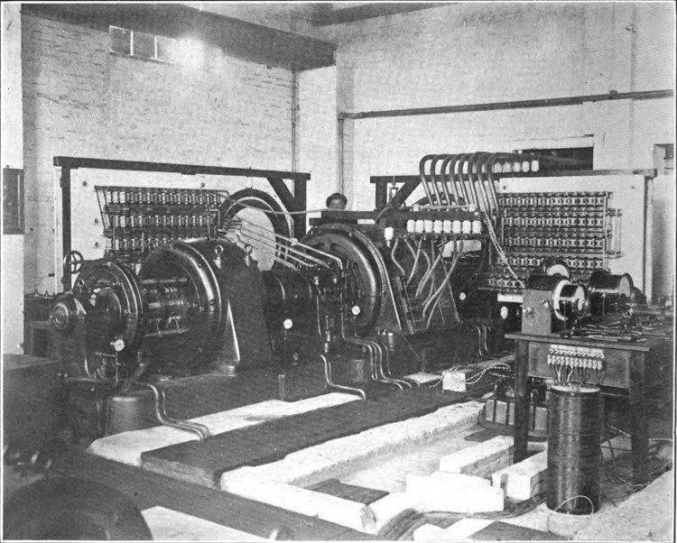
The machine was developed and manufactured by the German company Hochfrequenz-Maschinen Aktiengesellschaft für Drahtlose Telegraphie ("Homag") and was mostly used in Europe. The Goldschmidt machine, like the Alexanderson and other alternator transmitters, was used mainly for high power longwave stations that transmitted radiotelegraphy messages, both commercial stations that handled private traffic, and naval stations that kept governments in touch with their colonies and naval fleets. The first Goldschmidt machine in the UK, a 12 kW, 60 kHz transmitter was installed at Stough in 1912. A 100 kW, 400 pole unit (top of page) was put into operation at Eilvese, Neustadt-am-Ruebenberger, Germany, and the first machine in the USA was a similar 120 kW, 400 pole, 40.5 kHz unit at Tuckerton, New Jersey. A 250 kW unit installed at Laeken, Belgium in 1913 to communicate with Belgium's African colonies was destroyed by the Germans in 1914. The Eilvese machine was Germany's main communication channel with the world during World War I, and was used by Kaiser Wilhelm II and US President Woodrow Wilson to negotiate the Armistice that ended the war.
The heyday of the big alternator radio transmitters was around 1918. World War I had brought home to nations the strategic importance of radio communication, as without it they could easily be isolated by enemies cutting their submarine telegraph cables. This precipitated a postwar building boom of large transcontinental alternater radio stations. However these expensive behemoths were obsolete even as they were installed. The invention of the triode vacuum tube in 1906 by Lee De Forest, and the feedback oscillator circuit in 1912 by Edwin Armstrong and Alexander Meissner, made possible smaller and cheaper vacuum tube transmitters which by the end of World War 1 could produce as much radio power as the alternators. By 1921 the Marconi Co. had installed 100 kW vacuum tube transmitters for transatlantic message traffic at its stations at Carnarvon, Wales and Glace Bay, Newfoundland. Due to their huge capitol costs, legacy alternator transmitters remained in use through about 1930. It is not known when the last Goldschmidt machine was retired.
Other radio alternators
The Goldschmidt alternator was one of several types of rotating "radio frequency alternator" machines used as radio transmitters during the first two decades of the 20th century. Alternator transmitters produced a "cleaner" signal with less harmonics than their main competitor, the Poulsen arc transmitter so they were used in the highest power telegraphy stations. The machines differed in how they solved the fundamental problem of producing high frequencies without exceeding the mechanical capabilities of rotating machines: