General Electric's BWR product line of Boiling Water Reactors represents the designs of a large percent of the fission reactors around the world.
The progenitor of the BWR line was the 5MW Reactor at the Valiecitos Boiling-Water reactor in 1957.
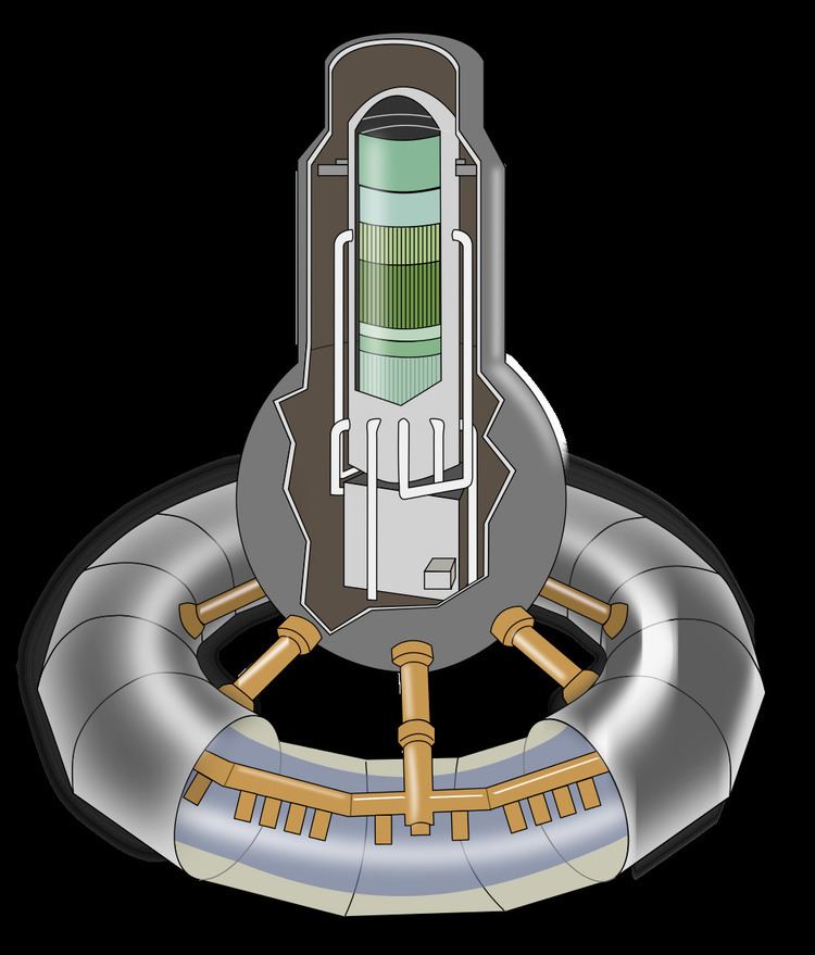
Elk River - 5x5 fuel rod bundle (ge bwr?)Lacrosse - 10x10 fuel rod bundle (ge bwr?)BWR Type 1: In 1955 GE developed this design into the 180MW Dresden 1(6x6,7x7) reactor, embodying GE's BWR/1 design. External or internal steam separation. GE would further develop this design with Big Rock Point(9x9, 11x11 12x12), and Humboldt Bay(6x6, 7x7), but sharing the BWR1 classification. These three experimental designs used fuel rod bundles in 6x6, 8x8, 9x9, 11x11, 12x12, but GE's 9x9 bundle later used in type 2-6 reactors is different from the one used in the Type 1 era. An example of designs later classified as Generation I reactor Humboldt Bay and Dodewaard had natural circulation. Type 1 was the first design with internal steam separation. It also had an isolation condenser, and pressure suppression containment.BWR Type 2: 1963 500MW Included a large direct cycle. 5 recirculation loops. This design, as well as types 3-6 would later be classed as Generation II reactors for their increased scale, and their design as commercially viable, profitable, long life reactors, designs that would become the foundation for the improved Generation III. Oyster Creek had a large direct cycle.BWR Type 3: Introduced in 1965 800MW (Dresden 2 & 3) Improved ECCS with spray and flood. First jet pump use (internal). 2 recirculation loops. Dresden 2 and Brown's Ferry had improved ECCS, spray and flood. They also had a reactor core isolation cooling system.BWR Type 4: Introduced in 1966 1,100MW (Decatur Al) Increased power density 20%.BWR Type 5: Introduced in 1969 (Moscow OH) Improved ECCS valve flow control. Recirculation flow control valves.BWR Type 6: Introduced in 1972, 1,390MW transitioned from 7x7 to 8x8 fuel bundle with longer, thinner rods, improved compact jet pumps with higher circulation and increased capacity of the steam separators and dryers, added fuel bundles, and increased output, reduced fuel duty, improved eccs, introduced a solid-state nuclear system protection system and reduced the size of the control room. A 1.22GW electrical BWR6 has 177 control rods and 748 fuel assemblies for a total of 46,376 fuel rods. It had a gravity containment flooder, and they had options for a compact control room, and only Clinton took the solid state nuclear system protection system.ABWR: Higher safety margins, no external recirculation loops, reactor internal pumps. It also has fine motion control rod drives.ESBWR: Passive safety, natural circulation (no loops or pumps), 1,600MW It has a gravity flooder, isolation condenser, and passive containment cooling.7x7 fuel bundle.Improved 7x7 fuel bundle with 49 fuel rods, one of which is segmented.8x8 fuel bundle with 63 fuel rods and 1 water rod.Retrofit 8x8 fuel bundle Prepressurized and Barrier fuel bundles containing 62 and two water rods.Prepressurized at 3ATM with helium with a Barrier8x8 fuel bundle with 58 to 62 fuel rods and 2-6 water rods. Prepressurized at 5ATM with helium.A drywell Containment building which resembles an inverted lightbulb above the wetwell which is a steel torus containing water.
Described as an "over-under" configuration with the drywell forming a truncated cone on a concrete slab. Below is a cylindrical suppression chamber made of concrete rather than just sheet metal.
The GE Mark III Containment is a single barrier pressure containment and multi-barrier fission containment system consisting of the containment vessel (pressure and fission barrier), the shield building, auxiliary building, and the fuel building, all of which are normally kept at negative pressure which prevents the egress of fission products.
Reduced reactor heightimproved seismic responseLower pressure containment designimprove pipe whip designcombines the cheaper dry containment with low pressure suppression type containmentOne advantage of the BWR design is improved load-following by virtue of control rod manipulation combined with changing the recirculation flow rate. The integration of the turbine pressure regulator and control system with the recirculation flow control system allows automatic power changes of up to 25% of rated power without altering control rod settings.Bottom entry bottom mounted control rods allow refueling without removal of the control rods and drives, while also allowing drive testing with an open vessel prior to fuel loading.BWR allow lower primary coolant flow than PWR.Jet pumps internal to the reactor vessel provide 2/3rds of the recirculation flow allowing the external recirculation flow loop to be small and compact compared to contemporary PWR designs.Under loss of coolant jet pumps provide 10% power similar to boilersBWR designs operate constantly at about half the primary system pressure of PWR designs while producing the same quantity and quality of steam in a compact system enabling a fast eccs.1020PSI Reactor Pressure Vessel pressure, and 288C temperature for BWR versus 2240psi and 326C for PWRsteam generated in reactor pressure vessel in BWR whereas it is generated in steam generator on a second loop in a PWRBWR allows for bulk boiling while PWR doesn't