
First appeared 1950s (first edition) | ||
 | ||
Filename extensions .mpt, .mpf .nc and several others | ||
G-code (also RS-274), which has many variants, is the common name for the most widely used numerical control (NC) programming language. It is used mainly in computer-aided manufacturing to control automated machine tools. G-code is sometimes called G programming language, not to be confused with LabVIEW's G programming language.
Contents
- Implementations
- Specific codes
- Letter addresses
- List of G codes commonly found on FANUC and similarly designed controls
- List of M codes commonly found on FANUC and similarly designed controls
- Example program
- Programming environments
- Abbreviations used by programmers and operators
- References
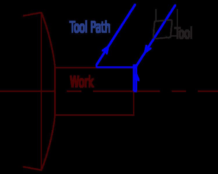
G-code is a language in which people tell computerized machine tools how to make something. The "how" is defined by instructions on where to move, how fast to move, and what path to follow. The most common situation is that, within a machine tool, a cutting tool is moved according to these instructions through a toolpath and cuts away material to leave only the finished workpiece. The same concept also extends to noncutting tools such as forming or burnishing tools, photoplotting, additive methods such as 3D printing, and measuring instruments.
Implementations
The first implementation of a numerical control programming language was developed at the MIT Servomechanisms Laboratory in the late 1950s. In the decades since, many implementations have been developed by many (commercial and noncommercial) organizations. G-code has often been used in these implementations. The main standardized version used in the United States was settled by the Electronic Industries Alliance in the early 1960s. A final revision was approved in February 1980 as RS-274-D. In other countries, the standard ISO 6983 is often used, but many European states use other standards. For example, DIN 66025 is used in Germany, and PN-73M-55256 and PN-93/M-55251 were formerly used in Poland.
Extensions and variations have been added independently by control manufacturers and machine tool manufacturers, and operators of a specific controller must be aware of differences of each manufacturer's product.
One standardized version of G-code, known as BCL, is used only on very few machines.
During the 1970s through 1990s, many CNC machine tool builders attempted to overcome compatibility difficulties by standardizing on machine tool controllers built by Fanuc. Siemens was another market dominator in CNC controls, especially in Europe. In the 2010s, controller differences and incompatibility are not as troublesome because machining operations are developed with CAD/CAM applications that can output the appropriate G-code for a specific machine tool.
Some CNC machines use "conversational" programming, which is a wizard-like programming mode that either hides G-code or completely bypasses the use of G-code. Some popular examples are Okuma's Advanced One Touch (AOT), Southwestern Industries' ProtoTRAK, Mazak's Mazatrol, Hurco's Ultimax, Haas' Intuitive Programming System (IPS), and Mori Seiki's CAPS conversational software.
G-code began as a limited type of language that lacked constructs such as loops, conditional operators, and programmer-declared variables with natural-word-including names (or the expressions in which to use them). It was unable to encode logic; it was just a way to "connect the dots" where many of the dots' locations were figured out longhand by the programmer. The latest implementations of G-code include such constructs, creating a language somewhat closer to a high-level programming language. Additionally, all primary manufacturers (e.g. Fanuc, Siemens, Heidenhain) provide access to PLC data, such as axis positioning data and tool data, via variables which can be used by NC programs. These constructs make it easier to develop automation applications.
Specific codes
G-codes are also called preparatory codes, and are any word in a CNC program that begins with the letter G. Generally it is a code telling the machine tool what type of action to perform, such as:
There are other codes; the type codes can be thought of like registers in a computer.
Students and hobbyists have pointed out over the years that the term "G-code" is imprecise. It comes from the literal sense of the term, referring to one letter address and to the specific codes that can be formed with it (for example, G00, G01, G28). But every letter of the English alphabet is used somewhere in the language. Nevertheless, "G-code" is established as the common name of the language.
Letter addresses
Some letter addresses are used only in milling or only in turning; most are used in both. Bold below are the letters seen most frequently throughout a program.
Sources: Smid 2008; Smid 2010; Green et al. 1996.
List of G-codes commonly found on FANUC and similarly designed controls
Sources: Smid 2008; Smid 2010; Green et al. 1996.
List of M-codes commonly found on FANUC and similarly designed controls
Sources: Smid 2008; Smid 2010; Green et al. 1996.
Example program
This is a generic program that demonstrates the use of G-Code to turn a 1" diameter X 1" long part. Assume that a bar of material is in the machine and that the bar is slightly oversized in length and diameter and that the bar protrudes by more than 1" from the face of the chuck. (Caution: This is generic, it might not work on any real machine! Pay particular attention to point 5 below.)
Several points to note:
- There is room for some programming style, even in this short program. The grouping of codes in line N06 could have been put on multiple lines. Doing so may have made it easier to follow program execution.
- Many codes are "modal", meaning that they stay in effect until they are cancelled or replaced by a contradictory code. For example, once variable speed cutting (CSS) had been selected (G96), it stayed in effect until the end of the program. In operation, the spindle speed would increase as the tool neared the center of the work in order to maintain a constant surface speed. Similarly, once rapid feed was selected (G00), all tool movements would be rapid until a feed rate code (G01, G02, G03) was selected.
- It is common practice to use a load monitor with CNC machinery. The load monitor will stop the machine if the spindle or feed loads exceed a preset value that is set during the set-up operation. The jobs of the load monitor are various:
- Prevent machine damage in the event of tool breakage or a programming mistake.
- This is especially important because it allows safe "lights-out machining", in which the operators set up the job and start it running during the day, then go home for the night, leaving the machines running and cutting parts during the night. Because no human is around to hear, see, or smell a problem such as a broken tool, the load monitor serves an important sentry duty. When it senses overload condition, which semantically suggests a dull or broken tool, it commands a stop to the machining. Technology is available nowadays to send an alert to someone remotely (e.g., the sleeping owner, operator, or owner-operator) if desired, which can allow them to come intercede and get production going again, then leave once more. This can be the difference between profitability or loss on some jobs, because lights-out machining reduces labor hours per part.
- Warn of a tool that is becoming dull and needs to be replaced or sharpened. Thus an operator who is busy tending multiple machines will be told by a machine, essentially, "Hey, pause what you're doing over there, and come attend to a need over here."
- Prevent machine damage in the event of tool breakage or a programming mistake.
- It is common practice to bring the tool in rapidly to a "safe" point that is close to the part—in this case 0.1" away—and then start feeding the tool. How close that "safe" distance is, depends on the preference of the programmer and/or operator and the maximum material condition for the raw stock.
- If the program is wrong, there is a high probability that the machine will crash, or ram the tool into the part under high power. This can be costly, especially in newer machining centers. It is possible to intersperse the program with optional stops (M01 code) which allow the program to be run piecemeal for testing purposes. The optional stops remain in the program but they are skipped during the normal running of the machine. Fortunately, most CAD/CAM software ships with CNC simulators that will display the movement of the tool as the program executes. Nowadays the surrounding objects (chuck, clamps, fixture, tailstock, and more) are included in the 3D models, and the simulation is much like an entire video game or virtual reality environment, making unexpected crashes much less likely. Many modern CNC machines also allow programmers to execute the program in a simulation mode and observe the operating parameters of the machine at a particular execution point. This enables programmers to discover semantic errors (as opposed to syntax errors) before losing material or tools to an incorrect program. Depending on the size of the part, wax blocks may be used for testing purposes as well.
- For educational purposes, line numbers have been included in the program above. They are usually not necessary for operation of a machine, so they are seldom used in industry. However, if branching or looping statements are used in the code, then line numbers may well be included as the target of those statements (e.g. GOTO N99).
- Some machines do not allow multiple M codes in the same line.
Programming environments
G-code's programming environments have evolved in parallel with those of general programming—from the earliest environments (e.g., writing a program with a pencil, typing it into a tape puncher) to the latest environments that combine CAD (computer-aided design), CAM (computer-aided manufacturing), and richly featured G-code editors. (G-code editors are analogous to XML editors, using colors and indents semantically [plus other features] to aid the user in ways that basic text editors can't. CAM packages are analogous to IDEs in general programming.)
Two high-level paradigm shifts have been (1) abandoning "manual programming" (with nothing but a pencil or text editor and a human mind) for CAM software systems that generate G-code automatically via postprocessors (analogous to the development of visual techniques in general programming), and (2) abandoning hardcoded constructs for parametric ones (analogous to the difference in general programming between hardcoding a constant into an equation versus declaring it a variable and assigning new values to it at will; and to the object-oriented approach in general). Macro (parametric) CNC programming uses human-friendly variable names, relational operators, and loop structures much as general programming does, to capture information and logic with machine-readable semantics. Whereas older manual CNC programming could only describe particular instances of parts in numeric form, macro programming describes abstractions which can be flowed with ease into a wide variety of instances. The difference has many analogues, both from before the computing era and from after its advent, such as (1) creating text as bitmaps versus using character encoding with glyphs; (2) the abstraction level of tabulated engineering drawings, with many part dash numbers parametrically defined by the one same drawing and a parameter table; or (3) the way that HTML passed through a phase of using content markup for presentation purposes, then matured toward the CSS model. In all of these cases, a higher layer of abstraction was introduced in order to pursue what was missing semantically.
STEP-NC reflects the same theme, which can be viewed as yet another step along a path that started with the development of machine tools, jigs and fixtures, and numerical control, which all sought to "build the skill into the tool". Recent developments of G-code and STEP-NC aim to build the information and semantics into the tool. The idea itself is not new; from the beginning of numerical control, the concept of an end-to-end CAD/CAM environment was the goal of such early technologies as DAC-1 and APT. Those efforts were fine for huge corporations like GM and Boeing. However, for small and medium enterprises, there had to be an era in which the simpler implementations of NC, with relatively primitive "connect-the-dots" G-code and manual programming, ruled the day until CAD/CAM could improve and disseminate throughout the economy.
Any machine tool with a great number of axes, spindles, and tool stations is difficult to program well manually. It has been done over the years, but not easily. This challenge has existed for decades in CNC screw machine and rotary transfer programming, and it now also arises with today's newer machining centers called "turn-mills", "mill-turns", "multitasking machines", and "multifunction machines". Now that CAD/CAM systems are widely used, CNC programming (such as with G-code) requires CAD/CAM (as opposed to manual programming) to be practical and competitive in the market segments served by these classes of machines. As Smid says, "Combine all these axes with some additional features, and the amount of knowledge required to succeed is quite overwhelming, to say the least." At the same time, however, programmers still must thoroughly understand the principles of manual programming and must think critically and second-guess some aspects of the software's decisions.
Since about the mid-2000s, the era has finally arrived when "the death of manual programming" (that is, of writing lines of G-code without CAD/CAM assistance) sometimes seems to be approaching. However, it is currently only in some contexts that manual programming is obsolete. Although it is true that plenty of CAM programming can and does take place nowadays among people who are rusty on, or incapable of, manual programming, it is not true that all CNC programming can be done, or done as well or as efficiently, without being able to speak the language of G-code. Tailoring and refining the CNC program at the machine is an area of practice where it can be easier or more efficient to edit the G-code directly rather than editing the CAM toolpaths and re-post-processing the program.
Abbreviations used by programmers and operators
This list is only a selection and, except for a few key terms, mostly avoids duplicating the many abbreviations listed at engineering drawing abbreviations and symbols (which see also).