
 | ||
A functional block diagram in systems engineering and software engineering is a block diagram. It describes the functions and interrelationships of a system.
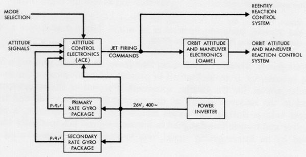
The functional block diagram can picture:
The block diagram can use additional schematic symbols to show particular properties.
Functional block diagrams have been used in a wide range applications, from systems engineering to software engineering, since the late 1950s. They became a necessity in complex systems design to "understand thoroughly from exterior design the operation of the present system and the relationship of each of the parts to the whole."
Many specific types of functional block diagrams have emerged. For example, the functional flow block diagram is a combination of the functional block diagram and the flow chart. Many software development methodologies are built with specific functional block diagram techniques. An example from the field of industrial computing is the Function Block Diagram (FBD), a graphical language for the design of programmable logic controllers.