
 | ||
Four-phase logic is a type of, and design methodology for, dynamic logic. It enabled non-specialist engineers to design quite complex ICs, using either PMOS or NMOS processes. It uses a kind of 4-phase clock signal.
Contents
History
R. K. "Bob" Booher, an engineer at Autonetics, invented four-phase logic, and communicated the idea to Frank Wanlass at Fairchild Semiconductor; Wanlass promoted this logic form at General Instrument Microelectronics Division. Booher made the first working four-phase chip, the Autonetics DDA integrator, during February 1966; he later designed several chips for and built the Autonetics D200 airborne computer using this technique.
In April 1967, Joel Karp and Elizabeth de Atley published an article "Use four-phase MOS IC logic" in Electronic Design magazine. In the same year, Cohen, Rubenstein, and Wanlass published "MTOS four phase clock systems." Wanlass had been director of research and engineering at General Instrument Microelectronics Division in New York since leaving Fairchild Semiconductor in 1964.
Lee Boysel, a disciple of Wanlass and a designer at Fairchild Semiconductor, and later founder of Four-Phase Systems, gave a "late news" talk on a four-phase 8-bit adder device in October 1967 at the International Electron Devices meeting. J. L. Seely, manager of MOS Operations at General Instrument Microelectronics Division, also wrote about four-phase logic in late 1967.
In 1968 Boysel published an article "Adder On a Chip: LSI Helps Reduce Cost of Small Machine" in Electronics magazine; Four-phase papers from Y. T. Yen also appear that year. Other papers followed shortly.
Boysel recalls that four-phase dynamic logic allowed him to achieve 10X the packing density, 10X the speed, and 1/10 the power, compared to other MOS techniques being used at the time (metal-gate saturated-load PMOS logic), using the first-generation MOS process at Fairchild.
Structure
There are basically two types of logic gate – a '1' gate and a '3' gate. These differ only in the clock phases used to drive them. A gate can have any logic function; thus potentially each and every gate has a customized layout. An example 2-input NAND 1 gate and an inverter 3 gate, together with their clock phases (the example uses NMOS transistors), are shown below:
The ϕ1 and ϕ3 clocks need to be non-overlapping, as do the ϕ2 and ϕ4 clocks. Considering the 1 gate, during the ϕ1 clock high time (also known as the precharge time) the output C precharges up to V(ϕ1)−Vth, where Vth represents the threshold of the precharge transistor. During the next quarter clock cycle (the sample time), when ϕ1 is low and ϕ2 is high, C either stays high (if A or B are low) or C gets discharged low (if A and B are high).
The A and B inputs must be stable throughout this sample time. The output C becomes valid during this time – and therefore a 1 gate output can't drive another 1 gate's inputs. Hence 1 gates have to feed 3 gates and they in turn have to feed 1 gates.
One more thing is useful – 2 and 4 gates. A 2 gate precharges on ϕ1 and samples on ϕ3:
and a 4 gate precharges on ϕ3 and samples on ϕ1.
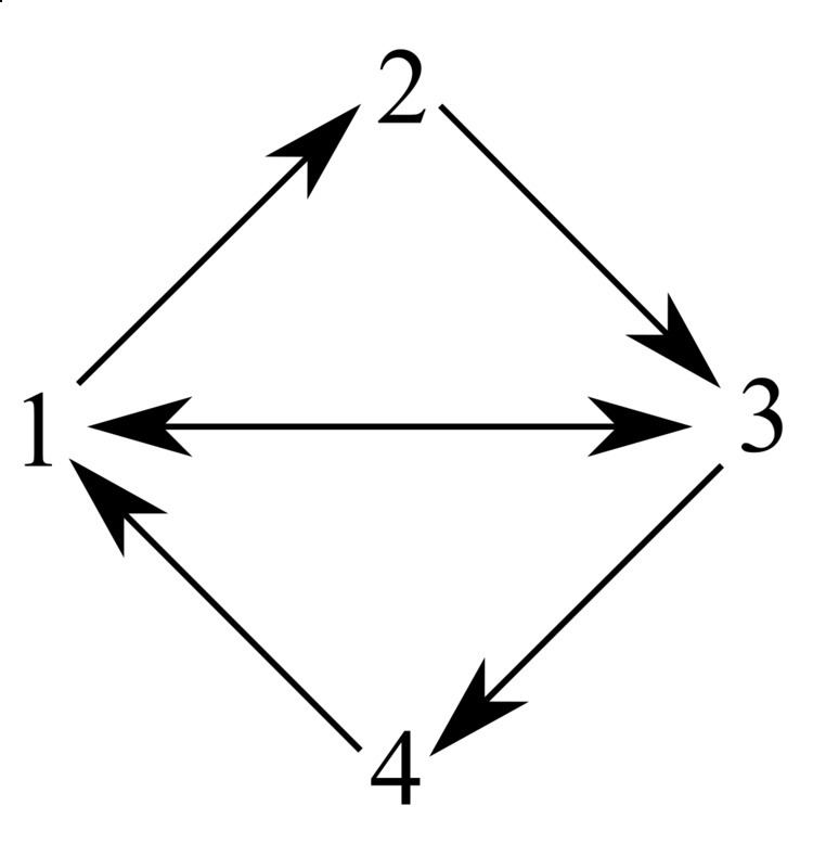
Gate interconnection rules are: 1 gates can drive 2 gates and/or 3 gates; 2 gates can drive only 3 gates, 3 gates can drive 4 gates and/or 1 gates, 4 gates can drive only 1 gates:
Usage
Four-phase logic works well; in particular there are no race hazards because every combinational logic gate includes a register. It's worth noting that the layout does not require the bussing of any power supplies – only clock lines are bussed. Also, since the design technique is ratioless (cf. static logic), many designs can use minimum-size transistors.
There are some difficulties:
Evolution
With the advent of CMOS, the precharge transistor could be changed to be the complement of the logic transistor type, which allows the gate's output to charge quickly all the way up to the high level of the clock line, thus improving the speed, signal swing, power consumption, and noise margin. This technique is used in domino logic.