
 | ||
A flow through cascade is a row of blades representing the blade ring of a turbo machine. These blades can be arranged in straight line or annular, thus representing an actual blade row, these arrangements are known as “rectilinear cascade” and “annular cascade” respectively. The “annular cascade” is more towards a real-life situation. The above arrangements are employed for the cascades of axial-flow turbo machines, but when the flow through the ring of blades is in the radial direction (inward or outward), the arrangement is termed as a “radial cascade”.
Contents
Testing
For simulation of actual condition cascade of blades are tested in annular form in wind tunnel, and as in rotating device it is difficult to appreciate flow physics generally straight cascade or cascade tunnel is used for testing. As a result it reduces mechanical complication and interpretation of test results get simplifies in 2-D flow conditions.
Two Dimensional Flow
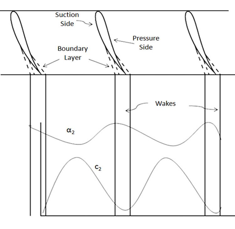
Due to rotation and boundary layer formation, flows in actual turbo machine is three dimensional. Assuming the flow to be two dimensional makes our problem quite easy. To do so we neglect the blade height. In axial machines flow is assumed to be two dimensional flow.In layman language three dimensional flow is reduced to two dimensional plane flow in which variations occur only in pitchwise and streamwise directions only. The boundary layer growth on the suction and pressure sides of the blades in a real flow leads to the formation of low energy regions in the exit flow field.The velocity (
Cascade Of Blades
Blades of a desired size and shape are assembled in a straight line or annular according to the cascade required. For assembling the blades, pitch(s) and stagger angle (γ). is defined. Blades of equal lengths are used in constructing a cascade. Blades for a cascade can be manufactured from wood, epoxy resin, glass wool, araldite or aluminium. Sometimes blades are made hollow to reduce the quantity of material and the weight of the blade. Generally, seven blades are used for cascade construction. The assembly is then fixed on the test section of the wind tunnel. Air at STP is blown over the cascade of blades to simulate the flow over an actual blade row in a turbo machine.
Measurement Of Static Pressure Distribution
Fig 2 shows the instrumented blade which shows the hypodermic tubes which are closed at one end and runs through the whole length of the blade. They are present on both sides of the blade surface. Open end of the tubes is projected through the side walls and is used to transmit the local static pressure to the manometer.
Cascade Performance
The main aim of cascade is to deflect the flow at desired angles. The deflection depends on the exit angles for a fixed entry angle and the exit varies with change in the pitch. The deflection occurs due to loss in stagnation pressure and increase in entropy and this is irreversible in nature.
The performance of a blade row (cascade) can be obtained by measuring the exit air angle (α2) and stagnation pressure loss (Δp0) across it. Due to two –dimensional flow variation of exit air angle α2 and Δp0 variation in the tangential direction, has to be taken into account. This is done by averaging the mass over the length of a blade in the tangential direction.
The mass flow rate through this elemental distance dy of unit length is
Mass-flow rate over one blade pitch
Tangential momentum of outgoing jet cx2
Similarly,
The mean value of the exit air angle of the cascade is obtained from Eqs
The integrated value of the stagnation pressure loss is
Velocity Triangles
Fig 3 shows the inlet,outlet and mean velocity triangles along with blade forces in a cascade. The velocity vectors c1 and c2 at the entry and exit are at air angles α1 and α2 respectively.
A mean velocity triangle for the flow through the cascade is defined by the following quantities
For constant axial velocity,
Blade Forces
The lift and the drag forces are perpendicular and parallel to the direction of the mean velocity
Tangential Forces
The tangential force on the blade is equal to the rate of change of momentum in the tangential direction. Using Fig 3, the following relation is obtained
Axial Forces
The axial force takes place due to both the pressure difference and change of momentum in the axial direction. Using fig 3,the following relation is obtained
Lift forces
Lift force L acts in the direction perpendicular to cm.The magnitude of lift force can be obtained by resolving the forces in velocity triangles in the direction of lift (Fig. 3), It is given by,
Drag Forces
The drag force D is in the direction of cm and is obtained by resolving forces in its direction
Losses
Losses in cascade occurs due to the three dimensional flow and the growth and separation of boundary layers that takes place on the surface of the blades. Other takes place due to the loss of stagnation pressure across the cascade and due to wasteful circulatory flows and the formation of shock waves.
Various types of losses are mentioned below
Profile Losses
It is the total loss in stagnation pressure across the blade row divided by the difference between the stagnation pressure and the static pressure at the outlet. It takes place due to the formation of boundary layer which steepens due to adverse pressure gradient.
Secondary Losses
It arises due to three dimensional flows near the end walls. The term secondary losses occurs due to the three-dimensional vortical flow structures that develop in blade passages due to high turning of the flow and nonuniform inlet total pressure profiles. Flow which is transverse to the primary flow direction is termed as secondary flow. The boundary layer flow along the endwall contains spanwise velocity gradients
Tip Clearance losses
Tip clearance flow is created by the fluid that passes through the radial gap between the tips of the rotor blades and the stationary rotor casing. About one third of the losses of a high-pressure stage can be due to the tip clearance flow, which deteriorates the aerodynamic and thermal performance of the axial flow turbine