
 | ||
Flight instruments are the instruments in the cockpit of an aircraft that provide the pilot with information about the flight situation of that aircraft, such as altitude, airspeed and direction. They improve safety by allowing the pilot to fly the aircraft in level flight, and make turns, without a reference outside the aircraft such as the horizon. Visual flight rules (VFR) require an airspeed indicator, an altimeter, and a compass or other suitable magnetic direction indicator. Instrument flight rules (IFR) additionally require a gyroscopic pitch-bank (artificial horizon), direction (directional gyro) and rate of turn indicator, plus a slip-skid indicator, adjustable altimeter, and a clock. Flight into Instrument meteorological conditions (IMC) require radio navigation instruments for precise takeoffs and landings.
Contents
- Flight Director Systems
- Layout
- T arrangement
- Early history
- Further development
- Different significance and some other instrumentation
- References
The term is sometimes used loosely as a synonym for cockpit instruments as a whole, in which context it can include engine instruments, navigational and communication equipment. Many modern aircraft have electronic flight instrument systems.
Most regulated aircraft have these flight instruments as dictated by the US Code of Federal Regulations, Title 14, Part 91. They are grouped according to pitot-static system, compass systems, and gyroscopic instruments.
The altimeter shows the aircraft's altitude above sea-level by measuring the difference between the pressure in a stack of aneroid capsules inside the altimeter and the atmospheric pressure obtained through the static system. It is adjustable for local barometric pressure which must be set correctly to obtain accurate altitude readings. As the aircraft ascends, the capsules expand and the static pressure drops, causing the altimeter to indicate a higher altitude. The opposite effect occurs when descending. With the advancement in aviation and increased altitude ceiling the altimeter dial had to be altered for use both at higher and lower altitudes. Hence when the needles were indicating lower altitudes i.e. the first 360 degree operation of the pointers was delineated by the appearance of a small window with oblique lines warning the pilot that he/she is nearer to the ground. This modification was introduced in the early sixties after the recurrence of air accidents caused by the confusion in the pilot's mind. At higher altitudes the window will disappear.
The airspeed indicator shows the aircraft's speed (usually in knots ) relative to the surrounding air. It works by measuring the ram-air pressure in the aircraft's Pitot tube relative to the ambient static pressure. The Indicated airspeed (IAS) must be corrected for nonstandard pressure and temperature in order to obtain the True airspeed (TAS). The instrument is color coded to indicate important airspeeds such as the stall speed, never-exceed airspeed, or safe flap operation speeds.
The VSI (also sometimes called a variometer, or rate of climb indicator) senses changing air pressure, and displays that information to the pilot as a rate of climb or descent in feet per minute, meters per second or knots.
The compass shows the aircraft's heading relative to magnetic north. Errors include Variation, or the difference between magnetic and true direction, and Deviation, caused by the electrical wiring in the aircraft, which requires a Compass Correction Card. Additionally, the compass is subject to Dip Errors. While reliable in steady level flight it can give confusing indications when turning, climbing, descending, or accelerating due to the inclination of the Earth's magnetic field. For this reason, the heading indicator is also used for aircraft operation, but periodically calibrated against the compass.
The attitude indicator (also known as an artificial horizon) shows the aircraft's relation to the horizon. From this the pilot can tell whether the wings are level (roll) and if the aircraft nose is pointing above or below the horizon (pitch). This is a primary instrument for instrument flight and is also useful in conditions of poor visibility. Pilots are trained to use other instruments in combination should this instrument or its power fail.
The heading indicator (also known as the directional gyro, or DG) displays the aircraft's heading with respect to magnetic north when set with a compass. Bearing friction causes drift errors from precession, which must be periodically corrected by calibrating the instrument to the magnetic compass. In many advanced aircraft (including almost all jet aircraft), the heading indicator is replaced by a horizontal situation indicator (HSI) which provides the same heading information, but also assists with navigation.
These include the Turn-and-Slip Indicator and the Turn Coordinator, which indicate rotation about the longitudinal axis. They include an inclinometer to indicate if the aircraft is in Coordinated flight, or in a Slip or Skid. Additional marks indicate a Standard rate turn.
Flight Director Systems
These include the Horizontal Situation Indicator (HSI) and Attitude Director Indicator (ADI). The HSI combines the magnetic compass with navigation signals and a Glide slope. The navigation information comes from a VOR/Localizer, or GPS. The ADI is an Attitude Indicator with computer-driven steering bars, a task reliever during instrument flight.
The VOR indicator instrument includes a Course deviation indicator (CDI), Omnibearing Selector (OBS), TO/FROM indicator, and Flags. The CDI shows an aircraft's lateral position in relation to a selected radial track. It is used for orientation, tracking to or from a station, and course interception.
The Automatic direction finder (ADF) indicator instrument can be a fixed-card, movable card, or a Radio magnetic indicator (RMI). An RMI is remotely coupled to a gyrocompass so that it automatically rotates the azimuth card to represent aircraft heading. While simple ADF displays may have only one needle, a typical RMI has two, coupled to different ADF receivers, allowing for position fixing using one instrument.
Layout
Most aircraft are equipped with a standard set of flight instruments which give the pilot information about the aircraft's attitude, airspeed, and altitude.
T arrangement
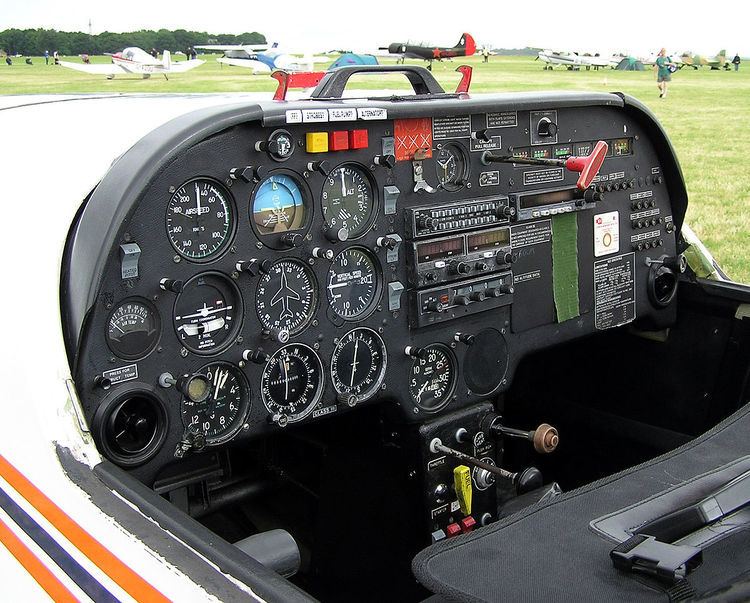
Most US aircraft built since the 1940s have flight instruments arranged in a standardized pattern called the "T" arrangement. The attitude indicator is in the top center, airspeed to the left, altimeter to the right and heading indicator under the attitude indicator. The other two, turn-coordinator and vertical-speed, are usually found under the airspeed and altimeter, but are given more latitude in placement. The magnetic compass will be above the instrument panel, often on the windscreen centerpost. In newer aircraft with glass cockpit instruments the layout of the displays conform to the basic T arrangement.
Early history
In 1929, Jimmy Doolittle became the first pilot to take off, fly and land an airplane using instruments alone, without a view outside the cockpit. In 1937, the British Royal Air Force (RAF) chose a set of six essential flight instruments which would remain the standard panel used for flying in instrument meteorological conditions (IMC) for the next 20 years. They were:
This panel arrangement was incorporated into all RAF aircraft built to official specification from 1938, such as the Miles Master, Hawker Hurricane, Supermarine Spitfire, and 4-engined Avro Lancaster and Handley Page Halifax heavy bombers, but not the earlier light single-engined Tiger Moth trainer, and minimized the type-conversion difficulties associated with blind flying, since a pilot trained on one aircraft could quickly become accustomed to any other if the instruments were identical.
This basic six set, also known as a "six pack", was also adopted by commercial aviation. After the Second World War the arrangement was changed to: (top row) airspeed, artificial horizon, altimeter, (bottom row) turn and bank indicator, heading indicator, vertical speed.
Further development
Of the old basic six instruments, the turn and bank indicator is now obsolete. The instrument was included, but it was of little use in the first generation of jet airliners. It was removed from many aircraft prior to glass cockpits becoming available. With an improved artificial horizon, including gyros and flight directors, the turn and bank indicator became needless except when performing certain types of aerobatics (which would not be intentionally performed in IMC to begin with). But the other five flight instruments, sometimes known as "the big five", are still included in all cockpits. The way of displaying them has changed over time, though. In glass cockpits the flight instruments are shown on monitors. But the display is not shown by numbers, but as images of analog instruments. The artificial horizon is given a central place in the monitor, with a heading indicator just below (usually this is displayed only as a part of the compass). The indicated airspeed, altimeter, and vertical speed indicator are displayed as columns with the indicated airspeed and altitude to the right of the horizon and the vertical speed to the left in the same pattern as in most older style "clock cockpits".
Different significance and some other instrumentation
In good weather a pilot can fly by looking out the window. However, when flying in cloud or at night at least one gyroscopic instrument is necessary to orientate the aircraft, being either an artificial horizon, turn and slip, or a gyro compass.
The vertical speed indicator, or VSI, is more of "a good help" than absolutely essential. On jet aircraft it displays the vertical speed in thousands of feet per minute, usually in the range -6 to +6. The gyrocompass can be used for navigation, but it is indeed a flight instrument as well. It is needed to control the adjustment of the heading, to be the same as the heading of the landing runway. Indicated airspeed, or IAS, is the second most important instrument and indicates the airspeed very accurately in the range of 45 to 250 knots. At higher altitude a MACH-meter is used instead, to prevent the aircraft from overspeed. An instrument called true airspeed, or TAS, exists on some aircraft. TAS shows airspeed in knots in the range from 200 knots and higher (It is like the Mach-meter: not really a flight instrument). The altimeter displays the altitude in feet, but must be corrected to local air pressure at the landing airport. The altimeter may be adjusted to show an altitude of zero feet on the runway, but far more common is to adjust the altimeter to show the actual altitude when the aircraft has landed. In the latter case pilots must keep the runway elevation in mind. However a radio altimeter (displaying the height above the ground if lower than around 2000–2500 feet) has been standard for decades. This instrument is however not among the "big five", but must still be considered as a flight instrument.