A flexible alternating current transmission system (FACTS) is a system composed of static equipment used for the AC transmission of electrical energy. It is meant to enhance controllability and increase power transfer capability of the network. It is generally a power electronics-based system.
FACTS is defined by the IEEE as "a power electronic based system and other static equipment that provide control of one or more AC transmission system parameters to enhance controllability and increase power transfer capability."
According to Siemens "FACTS Increase the reliability of AC grids and reduce power delivery costs. They improve transmission quality and efficiency of power transmission by supplying inductive or reactive power to the grid.
In shunt compensation, power system is connected in shunt (parallel) with the FACTS. It works as a controllable current source. Shunt compensation is of two types:
Shunt capacitive compensationThis method is used to improve the power factor. Whenever an inductive load is connected to the transmission line, power factor lags because of lagging load current. To compensate, a shunt capacitor is connected which draws current leading the source voltage. The net result is improvement in power factor.
Shunt inductive compensationThis method is used either when charging the transmission line, or, when there is very low load at the receiving end. Due to very low, or no load – very low current flows through the transmission line. Shunt capacitance in the transmission line causes voltage amplification (Ferranti effect). The receiving end voltage may become double the sending end voltage (generally in case of very long transmission lines). To compensate, shunt
inductors are connected across the transmission line. The power transfer capability is thereby increased depending upon the power equation
P = ( E V X ) sin ( δ )
δ = power angle
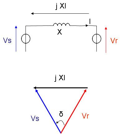
In the case of a no-loss line, voltage magnitude at the receiving end is the same as voltage magnitude at the sending end: Vs = Vr=V. Transmission results in a phase lag δ that depends on line reactance X.
V s _ = V cos ( δ 2 ) + j V sin ( δ 2 ) V r _ = V cos ( δ 2 ) − j V sin ( δ 2 ) I _ = V s _ − V r _ j X = 2 V sin ( δ 2 ) X
As it is a no-loss line, active power P is the same at any point of the line:
P s = P r = P = V cos ( δ 2 ) ⋅ 2 V sin ( δ 2 ) X = V 2 X sin ( δ )
Reactive power at sending end is the opposite of reactive power at receiving end:
Q s = − Q r = Q = V sin ( δ 2 ) ⋅ 2 V sin ( δ 2 ) X = V 2 X ( 1 − cos δ )
As δ is very small, active power mainly depends on δ whereas reactive power mainly depends on voltage magnitude.
FACTS for series compensation modify line impedance: X is decreased so as to increase the transmittable active power. However, more reactive power must be provided.
P = V 2 X − X c sin ( δ ) Q = V 2 X − X c ( 1 − cos δ )
Reactive current is injected into the line to maintain voltage magnitude. Transmittable active power is increased but more reactive power is to be provided.
P = 2 V 2 X sin ( δ 2 ) Q = 2 V 2 X [ 1 − cos ( δ 2 ) ]
Static synchronous series compensator (SSSC)Thyristor-controlled series capacitor (TCSC): a series capacitor bank is shunted by a thyristor-controlled reactorThyristor-controlled series reactor (TCSR): a series reactor bank is shunted by a thyristor-controlled reactorThyristor-switched series capacitor (TSSC): a series capacitor bank is shunted by a thyristor-switched reactorThyristor-switched series reactor (TSSR): a series reactor bank is shunted by a thyristor-switched reactorStatic synchronous compensator (STATCOM); previously known as a static condenser (STATCON)Static VAR compensator (SVC). Most common SVCs are:Thyristor-controlled reactor (TCR): reactor is connected in series with a bidirectional thyristor valve. The thyristor valve is phase-controlled. Equivalent reactance is varied continuously.Thyristor-switched reactor (TSR): Same as TCR but thyristor is either in zero- or full- conduction. Equivalent reactance is varied in stepwise manner. Thyristor-switched capacitor (TSC): capacitor is connected in series with a bidirectional thyristor valve. Thyristor is either in zero- or full- conduction. Equivalent reactance is varied in stepwise manner.Mechanically-switched capacitor (MSC): capacitor is switched by circuit-breaker. It aims at compensating steady state reactive power. It is switched only a few times a day.