
 | ||
A fiber optic patch cord is a fiber optic cable capped at either end with connectors that allow it to be rapidly and conveniently connected to CATV, an optical switch or other telecommunication equipment. Its thick layer of protection is used to connect the optical transmitter, receiver, and the terminal box. This is known as "interconnect-style cabling".
Contents
General Characteristics
Fiber optic patch cords are characterized by:
Construction
A fiber optic patch cord is constructed from a core with a high refractive index, surrounded by a coating with a low refractive index, that is strengthened by aramid yarns and surrounded by a protective jacket. Transparency of the core permits transmission of optic signals with little loss over great distances. The coating's low refractive index reflects light back into the core, minimizing signal loss. The protective aramid yarns and outer jacket minimizes physical damage to the core and coating.
Size
Ordinary cables measure 125 µm in diameter (a strand of human hair is about 100 µm). The inner diameter measures 9 µm for single-mode cables, and 50 / 62.5 µm for multi-mode cables.
The development of "reduced bend radius" fiber in the mid-2000s, enabled a trend towards smaller cables. Each unit of diameter reduction in a round cable, produces a disproportionate corresponding reduction in the space the cable occupies.
Classification
Patch cords are classified by transmission medium (long or short distance), by connector construction and by construction of the connector's inserted core cover.
Transmission medium
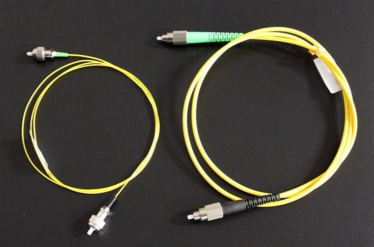
Single-mode fiber is generally yellow, with a blue connector, and a longer transmission distance. Multi-mode fiber is generally orange or grey, with a cream or black connector, and a shorter transmission distance.
Connector construction
Connector design standards include FC, SC, ST, LC, MTRJ, MPO, MU, SMA, FDDI, E2000, DIN4, and D4. Cables are classified by the connectors on either end of the cable; some of the most common cable configurations include FC-FC, FC-SC, FC-LC, FC-ST, SC-SC, and SC-ST.
Inserted core cover
The connector's inserted core cover conforms to APC, UPC, or PC configuration. A UPC inserted core cover is flat and is used in SARFT and early CATV. An APC connector's inserted core cover is oblique (about 30 °, ±5 °). To reduce the back reflection of a connector,UPC polish. Industry standard is a minimum of–40 dB for PC back reflec-tion measurement and–50 dB for UPC back reflection measurement. If even less back reflection is required, an APC might be necessary. An APC connector has an 8ºangle cut into the ferrule. These connectors are identifiable by their green color. An APC polished connector has an Indus-try Standard Minimum of–60 dB measurement. APC fiber ends have low back reflection even when disconnected.
Armored Fiber Patch Cord
Armored fiber optic patch cord uses flexible stainless steel tube inside the outer jacket as the armor to protect the fiber glass inside. It retains all the features of standard patch cord, but is much stronger. It will not get damaged even if stepped by an adult and they are rodent-resistant.
Bend Insensitive Fiber Optic Patch Cord
Bend insensitive fiber patch cord is widely used in FTTH. The fiber is not sensitive to stress and bending. Singlemode bend insensitive fibers include G657A1, G657A2, G657B2, and G657B3.
Mode Conditioning Patch Cord
Mode Conditioning Patch Cord is required where Gigabit 1000 Base-LX routers and switches are installed into existing multimode cable plants. The transceiver modules launch only singlemode 1300 nm signals but the existing network is built with multimode cables.
A single-mode laser launch into the center of a multimode fiber can generate multiple signals that confuse the receiver at the other end of the fiber. These multiple signals, caused by Differential Mode Delay (DMD) effects, limit the system distance lengths for operating Gigabit Ethernet. Mode Conditioning Patch Cord eliminates these multiple signals by aligning the single-mode launch away from the center of a multimode fiber core. This offset launch creates a transmitted signal that is similar to typical multimode light emitting diode (LED) launches.
Applications
Patch cables are used for connections to CATV (Cable Television), telecommunication networks, computer fiber networks and fiber test equipment. Applications include communication rooms, FTTH (Fiber to The Home), LAN (Local Area Network), FOS (fiber optic sensor), Fiber Optic Communication System, Optical fiber connected and transmitted equipment, Defense combat readiness, etc.