
 | ||
Fiber diffraction is a subarea of scattering, an area in which molecular structure is determined from scattering data (usually of X-rays, electrons or neutrons). In fiber diffraction the scattering pattern does not change, as the sample is rotated about a unique axis (the fiber axis). Such uniaxial symmetry is frequent with filaments or fibers consisting of biological or man-made macromolecules. In crystallography fiber symmetry is an aggravation regarding the determination of crystal structure, because reflexions are smeared and may overlap in the fiber diffraction pattern. Materials science considers fiber symmetry a simplification, because almost the complete obtainable structure information is in a single two-dimensional (2D) diffraction pattern exposed on photographic film or on a 2D detector. 2 instead of 3 co-ordinate directions suffice to describe fiber diffraction.
Contents
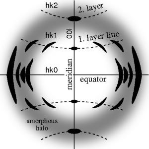
The ideal fiber pattern exhibits 4-quadrant symmetry. In the ideal pattern the fiber axis is called the meridian, the perpendicular direction is called equator. In case of fiber symmetry, many more reflexions than in single-crystal diffraction show up in the 2D pattern. In fiber patterns these reflexions clearly appear arranged along lines (layer lines) running almost parallel to the equator. Thus, in fiber diffraction the layer line concept of crystallography becomes palpable. Bent layer lines indicate that the pattern must be straightened. Reflexions are labelled by the Miller index hkl, i.e. 3 digits. Reflexions on the i-th layer line share l=i. Reflexions on the meridian are 00l-reflexions. In crystallography artificial fiber diffraction patterns are generated by rotating a single crystal about an axis (rotating crystal method).
Non-ideal fiber patterns are obtained in experiments. They only show mirror symmetry about the meridian. The reason is that the fiber axis and the incident beam (X-rays, electrons, neutrons) cannot be perfectly oriented perpendicular to each other. The corresponding geometric distortion has been extensively studied by Michael Polanyi introducing the concept of Polanyi's sphere (German: "Lagenkugel") intersecting Ewald's sphere. Later Rosalind Franklin and Raymond Gosling have carried out their own geometrical reasoning and presented an approximative equation for the fiber tilt angle β. Analysis starts by mapping the distorted 2D pattern on the representative plane of the fiber. This is the plane that contains the cylinder axis in reciprocal space. In crystallography first an approximation of the mapping into reciprocal space is computed that is refined iteratively. The digital method frequently called Fraser correction starts from the Franklin approximation for the tilt angle β. It eliminates fiber tilt, unwarps the detector image, and corrects the scattering intensity. The correct equation for the determination of β has been presented by Norbert Stribeck.
Historical role
Fiber diffraction data led to several important advances in the development of structural biology, e.g., the original models of the α-helix and the Watson-Crick model of double-stranded DNA.
Fiber diffraction geometry
The animation shows the geometry of fiber diffraction. It is based on the notions proposed by Polanyi. Reference direction is the primary beam (label: X-ray). If the fiber is tilted away from the perpendicular direction by an angle β, as well the information about its molecular structure in reciprocal space (trihedron labelled s-space) is tilted. In reciprocal space the Ewald sphere has its center in the sample. Its radius is 1/λ, with λ the wavelength of the incident radiation. On the surface of the Ewald sphere all the points of reciprocal space are found that are seen by the detector. These points are mapped on the pixels of the detector by central projection.
In s-space each reflexion is found on its Polanyi-sphere. Intrinsically the ideal reflexion is a point in s-space, but fiber symmetry turns it into a ring smeared out by rotation about the fiber direction. Two rings represent each reflexion on the Polanyi sphere, because scattering is point symmetric with respect to the origin of s-space. Mapped onto the detector are only those points of the reflexion in s-space that are both on the Ewald sphere and on the Polanyi sphere. These points form the reflexion circle (blue ring). It does not change as the fiber is tilted. As with a slide projector the reflexion circle is projected (red moving rays) on the detector (detector circle, blue ring). There up to 4 images (red spots) of the monitored reflexion can show up. The position of the reflexion images is a function of the orientation of the fiber in the primary beam (Polanyi equation). Inverted, from the positions of the reflexion images the orientation of the fiber can be determined, if for the Miller index
Pattern correction
The figure on the left shows a typical fiber pattern of polypropylene before mapping it into reciprocal space. The mirror axis in the pattern is rotated by the angle
After determination of
The three-dimensional sketch demonstrates that in the example experiment the collected information on the molecular structure of the polypropylene fiber is almost complete. By rotation of the plane pattern about the meridian the scattering data collected in 4 s fill an almost spherical volume of s-space. In the example the 4-quadrant symmetry has not yet been considered to fill part of the white spots. For clarity a quarter of the sphere has been cut out, but keeping the equatorial plane itself.